background image


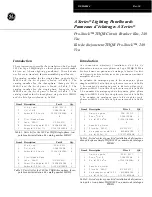
Figure 5. Close Coil Plug assembly 

 
8. Ensure the plug is inserted properly by the 

snap in the secondary disconnect.


9.


Place the ferrite from the coil assembly behind 

the coil. Route the wire from the close coil to the 
side of the PMU base for the connection with 
Electrical close switch as shown in fig.6. 


Figure 6. Close Coil wire routing 


Installation of Electrical close switch: 
 

10.


Slide the switch assembly over the 

mechanism side sheet and locate in the two 
locating holes as shown in Fig. 7. 


Figure 7.  EC switch assembly


11.


Assemble the screw with washer as shown 

in Fig. 8. Tighten the screw to torque  
2Nm(1.47ft-lbs). 


Figure 8. Screw assembly 


12. Plug the connector from the EC switch 
assembly to the connector from the command 
closing coil beside the PMU base as shown in 
Fig 9. 


Figure 9. Connector plug assembly 


Summary of Contents for GCCC024DR

Page 1: ...r 1 Verify that the rating on the Command Closing Coil identification plate matches the voltage rating required for the application as listed in Table 1 2 Turn the breaker off and discharge the closing springs by depressing the OFF and ON buttons in the sequence OFF ON OFF Verify that the breaker OFF ON indicator shows OFF on a green background and that the charge indicator shows DISCHARGE on a wh...

Page 2: ...mbly 5 Tilt the coil forward and engage the front hooks into the mechanism top support plate as shown in the Fig 3 Figure 3 Coil Assembly 6 Tilt the device backwards until the rear hooks engage in the slots on the mechanism top support plate as shown in the Fig 4 Figure 4 Coil Assembly 7 After installing the closing coil on the mechanism top plate connect the input wire assembly plug to the A9 A10...

Page 3: ...6 Figure 6 Close Coil wire routing Installation of Electrical close switch 10 Slide the switch assembly over the mechanism side sheet and locate in the two locating holes as shown in Fig 7 Figure 7 EC switch assembly 11 Assemble the screw with washer as shown in Fig 8 Tighten the screw to torque 2Nm 1 47ft lbs Figure 8 Screw assembly 12 Plug the connector from the EC switch assembly to the connect...

Page 4: ...with the screw washer as shown in fig 11 Fig 11 Push button assembly 15 Rotate the charging handle down and slide the front cover over the handle to assemble the front cover to housing as shown in Fig 12 Figure 12 16 Ensure the fascia is aligned properly with the trip unit and the pad lock features of the breaker 17 Fasten the 6 mounting screws of fascia with the housing using a pozidrive screwdri...

Page 5: ...ce Command Closing Coil Connection Scheme A10 provides constant control power to the Command Close Coil accessory A9 control power return A11 Separate local command input Must be fed from the same source as A10 ...

Page 6: ...Function Code 05 ON to register 111 The command will remain in effect until it is turned OFF To turn off the command send a COIL OFF command Modbus Function Code 05 OFF to register 111 Note that the remote command input must be set to OFF and the local command inputs must be OFF before the close coil can be retriggered with a new command Refer to DEH 4567 EntelliGuard Trip Unit Instruction for mor...

Reviews: