4 Operation
4.3 Setting up a run
30
Electrophoresis Power Supply EPS 3501 XL
Operating Instructions
28-9639-69
AA
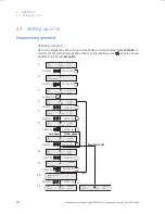
Table 4-1
and
Figure 4-2
illustrate a step program. The programming and running of this
application are shown as
Figure 4-1
and
Figure 4-5
.
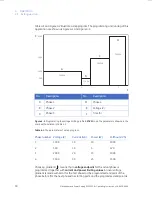
Figure 4-2.
Programming the voltage limiting profile in
STEP
mode. The parameters shown are the
same as those listed in
Table 4-1
.
Table 4-1.
The parameters of a step program.
Choosing gradient ( ), means that a
voltage endpoint
for the actual phase is
programmed together with
current and power limiting values
. A linear voltage
gradient is made with zero (for the first phase) or the programmed endpoint of the
phase before (for the next phases) as starting point and the programmed endpoint as
No.
Description
No.
Description
A
Phase 1
D
Phase 4
B
Phase 2
E
Voltage (V)
C
Phase 3
F
Time (h)
Phase number Voltage (V)
Current (mA)
Power (W)
Volthours (Vh)
1
1000
10
10
1000
2
500
10
5
120
3
2000
20
15
1000
4
3500
30
25
1500
500
1000
2000
3500
1000 Vh
120 Vh
1000 Vh
1500 Vh
1
2
E
F
A
B
C
D

