Optional Enclosures
C-1
March 2008
Introduction
Upon request the Model GS868 flowmeter may be supplied in an
enclosure other than the standard Type-4X enclosure described in
Chapter 1,
Installation
, of this manual. Although the standard
installation and wiring instructions still apply in general terms, some
of the details may vary for different enclosure types. Refer to the
appropriate sections of this appendix for the specific type of
enclosure provided.
Rack Mount Enclosure
The Model GS868 flowmeter is available in a
rack mount
enclosure
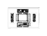
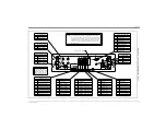
for installation in a standard 19” electronics rack. Refer to Figure C-1
on page C-3 for the dimensions of this unit. Simply slide the Model
GS868 into the rack at the desired height and fasten the unit securely
to the rack with four screws in the locations provided at the sides of
the front panel.
After the unit has been physically mounted into the rack, proceed to
the next section for instructions on wiring the meter.
Rack Mount Wiring
The rack mount Model GS868 requires exactly the same electrical
connections as the standard version. However, the locations and type
of connectors used for the various components are different. Refer to
Figure C-2 on page C-4 and complete the following steps:
1.
Wire the
power input
on the right side of the rear panel as follows:
a.
Make sure a
fuse
(item #4) of the proper size and type is
installed.
b.
Connect the female end of the
line cord
provided to the power
input receptacle (item #3).
c.
Connect the
earth ground
screw terminal (item #2) to a ground
point on the rack.
2.
Wire the
transducers
as follows:
a.
Connect the pair of cables supplied with the meter to the
Channel 1
upstream and downstream BNC transducer
connectors on the left side of the rear panel.
b.
For a 2-Channel meter, repeat the above step for the
Channel 2
transducer connectors (if the second channel is to be used).
c.
Complete the transducer wiring in accordance with the
instructions in Chapter 1,
Installation
, of this manual.
Summary of Contents for DigitalFlow GS868
Page 6: ...Chapter 1...
Page 28: ...Chapter 2...
Page 40: ...Chapter 3...
Page 41: ...Operation Introduction 3 1 Powering Up 3 2 Using the Display 3 3 Taking Measurements 3 5...
Page 49: ...Chapter 4...
Page 50: ...Specifications General 4 1 Electrical 4 2 Operational 4 4 Transducer 4 4 Flowcell 4 5...
Page 56: ...Appendix A...
Page 57: ...CE Mark Compliance Introduction A 1 Wiring A 1 External Grounding A 1...
Page 59: ...Appendix B...
Page 60: ...Data Records Option Cards Installed B 1 Initial Setup Data B 2...
Page 64: ...Appendix C...
Page 71: ...Appendix D...
Page 72: ...Measuring P and L Dimensions Introduction D 1 Measuring P and L D 1...

