


Installation
1-9
March 2008
Wiring the Transducers
ATTENTION EUROPEAN CUSTOMERS!
To meet CE Mark requirements, all cables must be installed
as described in Appendix A,
CE Mark Compliance
.
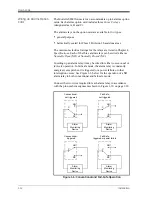
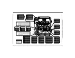
Wiring a typical Model GS868 ultrasonic natural gas flowmeter
system requires interconnection of the following components:
•
a pair of transducers (per channel) mounted in the flowcell
•
a preamplifier for each channel
•
a lightning protector (optional)
•
the electronics console
To wire the transducers, complete the following steps:
!WARNING!
Before connecting the transducers, take them to a safe
area and discharge any static buildup by shorting the
center conductor of the transducer cables to the metal
shield on the cable connector.
1.
Using the pair of coaxial cables with BNC to BNC connectors
supplied by the factory (or equivalent cables), connect both
transducers to the preamplifier.
Caution!
As part of maintaining the FM/CSA environmental rating
(NEMA/TYPE 4) on the remote preamplifier, thread sealant
is required on all conduit entries.
2.
If an optional lightning protector is being installed, connect it to
the preamplifier.
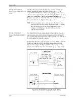
3.
Using the pair of coaxial cables with BNC to flying lead
connectors supplied by the factory (or equivalent cables), connect
the preamplifier to terminal block
CH1
in the electronics console.
Refer to Figure 1-10 on page 1-20 for the location of the terminal
block and the terminal block pin assignments.
4.
For a 2-channel Model GS868 flowmeter, repeat steps 1-3 to wire
the Channel 2 transducer system to terminal block
CH2
.
Note:
It is not required that Channel 2 of a 2-channel Model GS868
be used. This channel may be left inactive for future use.
After the wiring has been completed, the transducer channel(s) must
be activated before measurements can begin. See Chapter 2,
Initial
Setup
, for instructions.
Summary of Contents for DigitalFlow GS868
Page 6: ...Chapter 1...
Page 28: ...Chapter 2...
Page 40: ...Chapter 3...
Page 41: ...Operation Introduction 3 1 Powering Up 3 2 Using the Display 3 3 Taking Measurements 3 5...
Page 49: ...Chapter 4...
Page 50: ...Specifications General 4 1 Electrical 4 2 Operational 4 4 Transducer 4 4 Flowcell 4 5...
Page 56: ...Appendix A...
Page 57: ...CE Mark Compliance Introduction A 1 Wiring A 1 External Grounding A 1...
Page 59: ...Appendix B...
Page 60: ...Data Records Option Cards Installed B 1 Initial Setup Data B 2...
Page 64: ...Appendix C...
Page 71: ...Appendix D...
Page 72: ...Measuring P and L Dimensions Introduction D 1 Measuring P and L D 1...


