background image

February 2009

4-6

Programming Meter Settings

Adjusting Contrast

For more comfortable viewing in a particular environment, the 
CTF878 enables you to adjust the screen contrast. To adjust the 
screen contrast:

1.

From the Meter menu, scroll to the Contrast entry and press 

[ENTER]

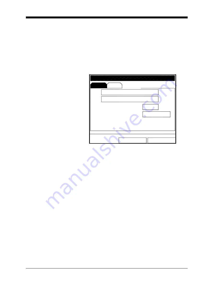
. The Display Options window opens on the Display tab, as 

shown in Figure 4-4 below. (From the Format tab, press the [

W

key to move to the Display tab.) To step through each parameter, 
press the [

T

] key.

Figure 4-4: Display Options Window - Display Tab

2.

Scroll to the Darker or Lighter box as desired.

3.

Press the 

[ENTER]

 button repeatedly until the screen has the desired 

contrast. 

Note:

If you find the screen has become too light or too dark, scroll 
to the other box and press 

[ENTER]

 until you have adjusted the 

screen to your satisfaction.

To confirm the entries and return to Operate Mode, press 

[F3]


(OK). The CTF878 returns to Operate Mode.

To leave the window without confirming the entries, press 

[F2]


(Cancel) or the 

[ESC]

 key. The CTF878 returns to Operate Mode.

Locale

OK

Cancel

Backlight Off

Language

English

Darker

Lighter

Min

1

Display Options

Display

Summary of Contents for CTF878

Page 1: ...GE Sensing Model CTF878 Clamp On Tag Flowmeter Programming Manual ...

Page 2: ...GE Sensing Model CTF878 Clamp On Tag Flowmeter Programming Manual 910 254PA4 February 2009 ...

Page 3: ...ose and warranties arising from course of dealing or usage or trade Return Policy If a GE Sensing Inc instrument malfunctions within the warranty period the following procedure must be completed 1 Notify GE giving full details of the problem and provide the model number and serial number of the instrument If the nature of the problem indicates the need for factory service GE will issue a RETURN AU...

Page 4: ...s 1 15 Path Parameters for Clamp On Transducers 1 16 Entering Analog Inputs 1 17 Entering Analog Outputs 1 20 Entering Digital Outputs 1 23 Entering Alarm Parameters 1 25 Entering Standard Volume Data 1 27 Entering Settings 1 27 Entering Inputs 1 28 Entering User Functions 1 30 Entering a Calibration Factor 1 33 Chapter 2 Displaying and Configuring Data Introduction 2 1 Format Option 2 2 View Opti...

Page 5: ...naming a Site 3 9 Deleting a Site 3 10 Listing Files by Name 3 11 Listing Files in Chronological Order 3 11 Chapter 4 Programming Meter Settings Introduction 4 1 Entering the Meter Menu 4 1 Selecting Measurement Units 4 2 Entering Date and Time 4 3 Changing Date and Time Appearance 4 4 Adjusting Contrast 4 6 Setting Backlight Timeout 4 7 Changing Communications Parameters 4 8 Resetting Forward and...

Page 6: ...leting All Logs 5 10 Refreshing the Log Manager Screen 5 10 Log Menu 5 11 Stopping Pausing a Log 5 11 Restarting a Log 5 11 Ending a Log 5 12 Stopping All Logs 5 12 Restarting All Logs 5 12 Ending All Logs 5 12 View All Sites 5 12 View Menu 5 13 Displaying Log Details 5 13 Displaying Log Data in Graphical Form 5 14 Displaying Log Data in Spreadsheet Form 5 17 Sort Menu 5 18 Listing Logs by Name 5 ...

Page 7: ...Chapter 1 ...

Page 8: ...ransducer Parameters 1 7 Entering Pipe Parameters 1 10 Entering Fluid Types and Speeds 1 14 Entering Path Parameters 1 15 Entering Analog Inputs 1 17 Entering Analog Outputs 1 20 Entering Digital Outputs 1 23 Entering Alarm Parameters 1 25 Entering Standard Volume Data 1 27 Entering User Functions 1 30 Entering a Calibration Factor 1 33 ...

Page 9: ...the more advanced features of the CTF878 but this information is not required to begin taking measurements Powering UP Immediately upon power up the CTF878 emits a short beep and displays a PCI Loader message It then validates the instrument programming and displays the GE Sensing logo and the software version If the meter fails any of these tests contact the factory After the meter conducts all t...

Page 10: ...those parts shown in Figure 1 2 below Figure 1 2 CTF878 Screen in Operate Mode The top line of the screen is the status bar which normally displays the time and date However when you press MENU the menu key the menu bar replaces the status line The middle of the screen is the work area which displays the measured parameters numeric measurements and both bar and line graphs When you enter a selecti...

Page 11: ...the screen displays the three function key options F1 F2 and F3 These keys have different functions depending on the task being performed The initial factory setup configuration for these keys is as follows F1 Transducer F2 Diagnostics F3 Save Now Table 1 1 Icons in the System Tray Icon Function Meaning Alert The meter encountered an error in operation Log A log is running marks Log A log is pendi...

Page 12: ...eys that are labeled with their functions The complete keypad is illustrated in Figure 1 3 below and a detailed description of the functions for each of the 24 keys is listed in Table 1 2 on page 1 5 Figure 1 3 CTF878 Keypad ENTER MENU ESC SEL 7 4 1 0 8 5 2 9 6 3 F1 F2 F3 CTF878 Flowmeter ...

Page 13: ...ices in measurement mode or to scroll through menu choices in programming mode Press as a backspace key in programming mode Help Key Use to access on line help See the next section for details Escape Key Press to exit menus or menu options at any time or cancel a numeric entry Select Key Use to move between data measurements on the screen Menu Key Press to access the Main Menu Enter Key Use to ent...

Page 14: ... through the available parameters The S key to scroll back to a previously entered parameter The F2 key Cancel or the ESC key to exit an option at any time and return to Operate Mode without changing the parameters Note The Transducer Pipe Fluid and Path parameters are categorized under the same Transducer Pipe menu as shown in Figure 1 5 below You can be more time efficient by programming the par...

Page 15: ...itself or to specify that you are using a special application transducer 1 From the Type prompt press the T key to reach the Transducer prompt and press ENTER 2 A drop down list of transducer numbers opens see Figure 1 6 below Press the T or S keys to scroll to the appropriate number or scroll to Special for a special application transducer 3 Press ENTER to confirm your selection Figure 1 6 Transd...

Page 16: ...nal order see Table 1 3 below 4 Compare the Receiver Board option number listed on the WARNING screen with the one assigned to your CTF878 Note The Receiver Board option number is the last digit of the CTF878 s model number That model number can be found on the label attached to the inside of the front cover In Figure 1 8 below the Receiver Board option number is 3 Figure 1 8 Transducer Type Optio...

Page 17: ...ial transducer receiver option The user must enter the appropriate transducer receiver operating frequency range IMPORTANT The CTF878 flowmeter and the transducers have the same fixed frequency band of operation defined by the customer s application The frequency printed on the transducers represents a frequency band of operation and does not always match the up or down frequencies 1 From the Tran...

Page 18: ... Transducer window you can scroll back up to the Transducer tab and press the X arrow key to reach the Pipe window and press ENTER The screen appears similar to Figure 1 9 below To step through each parameter press the T key See the Program Menu Map Figure 1 34 on page 1 37 Note Refer to the installation reference Sound Speeds and Pipe Size Data 914 004 for additional information about pipe sizes ...

Page 19: ...n Steel 1 Carbon hardened Steel Carbon Steel Mild Steel Stainless 302 Steel Stainless 303 Steel Stainless 304 Transduc Mate OD mm Nominal Copper Aluminum rolled Brass Copper annealed Copper rolled Copper Nickel 10 Copper Nickel 30 Glass Pyrex Transduc Mate OD mm Nominal Gold hard drawn Inconel Iron Armco Iron Cast Iron Ductile Iron electrolytic Monel Nickel Plastic Acrylic Steel Stainless 347 Stee...

Page 20: ...ircumference The prompt moves to the outside diameter OD text box Type the OD in mm or in whichever is displayed into the box and press ENTER to confirm your choice or Move the prompt to the circumference ODxPI text box Type the circumference in mm or in whichever is displayed into the text box and press ENTER to confirm the choice b In either case the next prompt asks for the wall thickness Type ...

Page 21: ... b Press the W key twice to move the prompt to the Nominal pipe size drop down menu Press ENTER to open the menu Scroll to the desired pipe size and press ENTER to confirm your choice c Press the X key to move the prompt to the Schedule drop down menu Press ENTER to open the menu Scroll to the desired schedule and press ENTER to confirm the choice To confirm the entries and return to Operate Mode ...

Page 22: ...ct the fluid 1 Press ENTER to open the drop down menu 2 Use the T key to scroll to the appropriate option 3 Press ENTER to confirm your selection Note If you select Air or Natural Gas the meter sets the soundspeed and suggests a value for K V x 10 6 If you wish you can change the value of K V x 10 6 If you select Other you must enter values for Sound Speed and for K V x 10 6 see Installation Refer...

Page 23: ...turns to Operate Mode Entering Path Parameters To enter the Path option scroll to the Path tab on the Program Menu and press ENTER From the Fluid window you can scroll back up to the Fluid tab and press ENTER The screen appears similar to Figure 1 13 below To step through each parameter press the T key Refer to Program Menu Map Figure 1 34 on page 1 37 Figure 1 13 Path Window Transducer Pipe Fluid...

Page 24: ...mping fixture it must be within 10 of the original TAG Path calculated by the flowmeter The Transducer Spacing is calculated from the data entered in the Transducer Pipe Fluid parameters The value of Transducer Spacing is NOT used in the flowmeter s data processing unlike the Tag Path Do not attempt to change the Transducer Spacing in the instrument It is only an output intended to tell the user t...

Page 25: ...card is installed Cards are numbered from right to left The number shown in parentheses is the option card slot number 1 Scroll to AnalogIns and press ENTER to confirm your selection Another drop down menu as in Figure 1 16 below appears Figure 1 16 Analog Inputs Option Window Transducer Site Program Meter Logging Service Pipe Fluid Path Standard Volu User Functions Correction Fac Analog Outputs 2...

Page 26: ...7 below Note The units for pressure and temperature are based on the settings in the Meter Units menu Figure 1 17 Function Menu Options 3 The next prompt asks you to create a name for a special function if desired see Figure 1 18 below Figure 1 18 Analog Input Information 4 20 In Setup Off Span Zero Units Function OK Cancel Pressure Temperature Label Special 4 20 In Setup Off Off Special Span Zero...

Page 27: ...ish to delete a letter press F1 Delete to erase each letter or symbol from right to left on the label d When you have completed the label press F3 OK to confirm the label or F2 Cancel to leave the window without adding the label 4 The next three prompts ask for the function units the zero input value and the span input value For each prompt a Press ENTER to enter the text box b Use the numeric key...

Page 28: ...rom right to left Figure 1 20 Analog Output Option Window The screen appears similar to Figure 1 21 below To step through each parameter press the T key See the Program Menu Map Figure 1 35 on page 1 38 Figure 1 21 Analog Output Window Transducer Site Program Meter Logging Service Pipe Fluid Path Standard Volu User Functions Correction Fac Main Board 0 0 50 100 AnalogOut 2 B AnalogOut 2 C AnalogOu...

Page 29: ... measurement type from a list of choices see Figure 1 23 on page 1 22 a Press ENTER to open the window b Scroll to the desired output type c Press SEL to confirm your selection d The prompt then moves to a list of unit types The available units depend on the selection made at the Data Source prompt Scroll to the desired output unit e Press F3 OK to confirm your selection 3 The next prompt requests...

Page 30: ...tion The meter offers three alternatives Hold Last Value hold the last good reading Force Low force the reading to 0 or 4 mA Force High force the reading to 20 mA a Press ENTER to open the drop down menu b Scroll to the desired selection c Press ENTER to confirm your selection You have completed entering data in the Analog Output option To confirm the entries and return to Operate mode press F3 OK...

Page 31: ...rom right to left The screen appears similar to Figure 1 24 below To step through each parameter press the T key Refer to the Program Menu Map Figure 1 36 on page 1 39 Figure 1 24 Digital Output Window 1 The first prompt enables you to select the output function from three choices Off Pulse Totalizer Frequency a Press ENTER to open the drop down menu b Scroll to the desired function c Press ENTER ...

Page 32: ...tput unit e Press F3 OK to confirm your selection 3 The last set of parameters that appears depends on the selection you made at the Function prompt If you selected Pulse Totalizer The prompt asks for the units pulse and the pulse width in microseconds Figure 1 24 on page 1 23 illustrates a Digital Output window configured for the Pulse Totalizer function For the Units Pulse and Pulse Width parame...

Page 33: ...d is installed Cards are numbered from right to left The screen appears similar to Figure 1 25 below To step through each parameter press the T key Refer to the Program Menu Map Figure 1 36 on page 1 39 Figure 1 25 Alarm Setup Window 1 The first prompt enables you to select the function from four choices Disabled High Low and All Faults a Press ENTER to open the drop down menu b Scroll to the desi...

Page 34: ... at the Data Source prompt Scroll to the desired output unit e Press F3 OK to confirm your selection Figure 1 26 Data Source Selection Window 3 Scroll to the next prompt and press ENTER to select or deselect the Failsafe option If Failsafe is selected an X will appear in the box 4 The next prompt asks for the Trigger Point frequency a Press ENTER to open the text box b Use the numeric keys to ente...

Page 35: ...ow Settings 1 The first prompt allows you to enable or disable the Standard Volume settings a Use the arrow keys to move to the appropriate choice b Press ENTER to confirm your choice Note If you selected Enabled continue on to step 2 to enter values for the three categories If you selected Disabled you will not be able to access the three boxes or the Inputs entry 2 To enter numbers for the three...

Page 36: ...pt allows you to fix the Pressure value or to render it active a Use the arrow keys to move to the appropriate choice b Press ENTER to confirm your choice Note If you selected Fixed continue on to step 2 to enter a value for the pressure If you selected Active you will not be able to enter the Pressure box and must proceed to step 3 2 To enter a value for the pressure a Press the T key to move to ...

Page 37: ...ess ENTER to confirm your choice Note If you selected Fixed continue on to step 5 to enter a value for the temperature If you selected Active you will not be able to enter the Temp box and must proceed to step 6 5 To enter a value for the temperature a Press the T key to move to the Temp box b Press ENTER and use the number keys to enter a value for the temperature c Press ENTER to confirm your en...

Page 38: ...efer to the Program Menu Map Figure 1 34 on page 1 37 Figure 1 29 User Function Window 1 The first prompt requests the function number 1 through 8 a Press ENTER to open the drop down menu b Scroll to the desired function number User1 User2 etc c Press ENTER to confirm the entry 2 The next prompt asks you to create a label for the function Note The label corresponds to the measurement type i e velo...

Page 39: ...press F1 Delete to erase each letter or symbol from right to left on the label d When you have completed the label press F3 OK to confirm the label or F2 Cancel to leave the window without adding the label 3 The next prompt asks for the Units Symbol a Press ENTER to reopen the text creation window b Repeat the procedure used for the Label above to create the Units Symbol c When you have completed ...

Page 40: ...tion Figure 1 31 Function Creation Window c To enter a particular measured parameter into the equation click on the MODE symbol near the middle of the third row The Select Measurement window shown in Figure 1 23 on page 1 22 opens Select the desired data source and unit see page 1 23 and press F3 OK to confirm the entry d When you have completed entering the function press F3 OK to confirm the ent...

Page 41: ...igure 1 34 on page 1 37 Figure 1 32 Calibration Factor Window 1 To enable or disable the Calibration Factor scroll down to the next line and select On or Off a Use the W and X keys to scroll to the appropriate option b Press ENTER to confirm your selection 2 If On is selected for the Calibration Factor scroll down to choose a Single K Factor or a Table of K Factors a Use the W and X keys to scroll...

Page 42: ...ithout confirming the entries press F2 Cancel or the ESC key The CTF878 returns to Operate Mode If you selected Table The menu asks first for the data source and then for the entry of values into the Correction Factor table This feature allows the user to curve fit velocity calibration multiple data points from several different data sources or flow variables to the flow rate reported by the CTF87...

Page 43: ... steps 7 8 and 9 for the remainder of the table 11 When you have completed entering values press F3 OK to confirm the table and return to the Correction Factors window You have completed entering data for correction factors To confirm the entries and return to Operate mode press F3 OK The CTF878 returns to Operate Mode To leave the window without confirming the entries press F2 Cancel or the ESC k...

Page 44: ...Path Txdr Spacing Brass Aluminum DIN Wall Thickness OD or ODxPI F2 not accept F3 accept or See following figures Settings Inputs Base Press Atmos Press Base Temp Enabled Disabled User8 User7 User6 User5 User4 User3 User2 User1 Type name name Type 3 4 1 2 0 Factor Calibration On Off Table Single Data Source Wall Thickness OD or ODxPI Meter K Factor Sound Speed Active Fixed Standard Volume Active Fi...

Page 45: ...3 3 meters hr 3 3 3 Velocity m s UserF8 UserF7 UserF6 UserF5 UserF4 UserF3 UserF2 UserF1 MMHG KPA Pressure Bars Temp K Temp C Hectare cm Fwd liters Fwd m Elapsed Hectare m Elapsed Hectare m Hectare cm Rev liters Rev m Elapsed Hectare m Hectare cm Fwd m Fwd liters Elapsed Hectare m Rev liters Rev m Hectare cm F2 not accept F3 accept or Program Hold Last Force High Force Low C 5 B C 4 B C 5 A C 4 A ...

Page 46: ...ters Rev m Elapsed Fwd m Fwd liters Elapsed Rev liters Rev m Function Off Pressure Units Zero Span Frequency Function Off 3 RTDs 4 RTD 4 B RTD 4 A Span Function Data Source Function Data Source Menu Site Meter Logging Service Transducer Pipe Path IO Std Volume User Func Cor Factors Fluid F2 not accept F3 accept or Program On Label Zero Special Label Alarm 3 C Alarms 3 Alarm 3 A Alarm 3 B All Fault...

Page 47: ...Chapter 2 ...

Page 48: ...Displaying and Configuring Data Introduction 2 1 Format Option 2 2 View Option 2 3 Limits Option 2 3 Measurement Option 2 5 Customizing the Display Screen 2 6 Accessing Meter Data The About Option 2 10 ...

Page 49: ...Mode window A cursor appears next to the parameter closest to the upper left corner Continuing to press SEL enables the cursor to scroll through the other displayed measurements Once you have reached a particular window pressing the ENTER button opens the menu for that window as shown in Figure 2 1 below To learn how to use the display window menu go to Format Option on page 2 2 View Option on pag...

Page 50: ...eric format from three choices default fixed decimal and scientific Default provides the default resolution while Fixed Decimal allows users to override the standard resolution Scientific format displays the value in mantissa and exponent format a Press ENTER to open the drop down list of format choices b Scroll to the appropriate selection c Press ENTER to confirm your choice 2 The second step as...

Page 51: ...ure 2 3 below Figure 2 3 Screen After Format Change Limits Option Once you have configured a parameter as a line or bar graph you might need to change its presentation or values The Limits option replacing the Format option for line and bar graphs enables you to program the minimum or maximum values displayed the time interval and the display of the average value To enter the Limits option 1 Press...

Page 52: ...rm the value b The second box asks for the interval in terms of seconds minutes hours or days Press ENTER to open the drop down menu and then press the T or S keys to move to the desired parameter Press ENTER to confirm the entry 8 The final three prompts ask for details of the graph configuration if you want to use lines plot the average value or show the minimum and maximum values Press the T ke...

Page 53: ...imilar to Figure 2 5 below The left column displays categories of data while the right column displays English and metric measurement units or with the Diagnostics source shown a list of diagnostics parameters 4 Use the T and S arrow keys to reach the desired category of data and press SEL 5 Then use the T or S arrow keys to select the desired measurement unit or diagnostic parameter Press F3 OK t...

Page 54: ...he Menu Bar replaces the Status Bar at the top of the screen Scroll to the Site Menu using the W or X key Press ENTER or the T arrow key The screen now appears similar to Figure 2 6 below While following the programming instructions refer to Figure 3 13 on page 3 12 Figure 2 6 Site Menu To specify the number of parameters displayed go to page 2 7 To customize or clear softkeys FKeys go to page 2 8...

Page 55: ...splays the designated number of windows For example Figure 2 7 below shows the screen displayed in Figure 2 3 on page 2 3 reconfigured for a single view Figure 2 7 Display Screen Configured for Single View Note The CTF878 opens display windows from left to right and from top to bottom starting from the upper left that is if you press 1 View the parameter displayed in the upper left window appears ...

Page 56: ...1 From the Site Menu shown in Figure 2 6 on page 2 6 use the T or S arrow keys to move to the FKeys entry on the menu Press ENTER The screen now appears similar to Figure 2 8 below Figure 2 8 FKeys Menu 2 Use the T or S arrow keys to move to the desired FKey 1 2 or 3 entry on the menu Press ENTER The Configure FKey window opens as shown in Figure 2 9 below Figure 2 9 Configure FKey Window Program ...

Page 57: ... Manager Pressing F1 opens the Site Manager window To customize a softkey from a particular menu 1 Open the desired menu on the Menu Bar see other chapters for details on particular menus and scroll to the desired option 2 Press the desired softkey A window appears with the question Assign current menu command to FKeyX 3 Press F3 Yes to confirm the assignment and close the window Press F2 No to cl...

Page 58: ...hange site files Accessing Meter Data The About Option The About option displays useful information concerning the model number and software version of any given CTF878 While the window normally appears briefly at startup users might want to access the information for a longer period To open the About window scroll to the About option on the Site Menu and press ENTER The screen appears similar to ...

Page 59: ...Chapter 3 ...

Page 60: ...Creating and Managing Sites Introduction 3 1 Site Manager 3 2 ...

Page 61: ... revert to or delete site files as needed To open the Site Menu press the MENU key at the lower right side of the CTF878 keypad The Menu Bar replaces the Status Bar at the top of the screen Scroll to the Site Menu using the W or X key Then press ENTER The screen now appears similar to Figure 3 1 below To manage the site files use the following instructions and refer to Figure 3 13 on page 3 12 Fig...

Page 62: ...h a basic site Default which serves as a basis for saving data and creating other sites The right section of the screen supplies information for the site highlighted in the list on the left its date time and size as well as the remaining amount of free memory You can use the T and S arrow keys to scroll to a particular site and display information pertaining to that site To open the Site Manager m...

Page 63: ...Saving a Site with a Different Name on page 3 8 Refreshing a Site on page 3 8 Renaming a Site on page 3 9 Deleting a Site on page 3 10 Arrange files from the Sort submenu see Figure 3 12 on page 3 11 Listing Files by Name on page 3 11 Listing Files in Chronological Order on page 3 11 Exit Refresh File Sort Info DEFAULT SIT New Site 00 02 04 11 24 27 5849 bytes 119808 bytes free Open Save Save As R...

Page 64: ... screen appears similar to Figure 3 4 below Figure 3 4 Name Entry Window for a New Site 1 Use the four arrow keys to scroll to the desired letter or number and press ENTER 2 Repeat this procedure until you have created the desired site name of up to eight characters Press F1 Delete to remove any unwanted letters or numbers 3 When you have finished press F3 OK to confirm the entry or F2 Cancel to l...

Page 65: ...a To modify the display and measurements refer to Chapter 2 Displaying and Configuring Data To alter programming data see Chapter 1 Programming Site Data Press F2 No to reject it or Press F3 Yes to use it as a template Figure 3 5 Template Confirmation Window The meter returns to Operate Mode with the new site name displayed in the upper left corner of the screen Yes No 6 Y Q I A 5 X P H Site Use t...

Page 66: ...below Figure 3 6 Open Site Confirmation Window Press F2 No to cancel opening the site and return to the current site or Press F3 Yes to open the site If you have changed the current site the CTF878 asks if you want to save the changes to the previously opened site Press F2 No to cancel the changes or Press F3 Yes to confirm and save the changes The CTF878 returns to Operate Mode with the selected ...

Page 67: ...ager press MENU to open the File Menu scroll to the Save option and press ENTER In either case the screen appears similar to Figure 3 7 below Figure 3 7 Save Current Site Window Press F2 No to cancel saving the site or Press F3 Yes to save the site The CTF878 remains in the current window Operate Mode or Site Manager with the current site saved Yes No Save the current site SITE03 SIT Site Manager ...

Page 68: ...When you have finished Press F2 Cancel to erase the entry or Press F3 OK to confirm the entry The Save Site window then appears Press F2 No to cancel saving the site or Press F3 Yes to save the site The CTF878 remains in Site Manager with the current site saved under both the old and new names Refreshing a Site You can refresh a site updating the display with the most current information in one of...

Page 69: ...re 3 9 Rename Site Window Use the four arrow keys to scroll to the desired letter or number and press ENTER Repeat this procedure until you have created the desired site name Press F1 Delete to remove any unwanted letters or numbers When you have finished Press F2 Cancel to erase the entry or Press F3 OK to confirm the entry The CTF878 remains in Site Manager with the site listed under the new nam...

Page 70: ...ppears see Figure 3 10 below Press F3 OK to return to the File Menu Figure 3 10 Site Error Window Otherwise the screen appears similar to Figure 3 11 below Figure 3 11 Delete Confirmation Window Press F2 No to cancel the deletion and return to the Site Manager or Press F3 Yes to delete the site The Site Manager appears and deletes the highlighted site OK You can not delete the Current Site Open an...

Page 71: ...phabetical order Figure 3 12 Sort Submenu Listing Files in Chronological Order To list your files chronologically by time of creation within the Site Manager press MENU to open the File Menu Press the X arrow key to scroll to the Sort Menu then scroll to the By Date option Press ENTER The Site Manager screen refreshes with the sites listed in chronological order from the most recent to the earlies...

Page 72: ...View 4 View FKeys About New Open Save Save As 2 View File Sort Clear F3 Clear F2 Clear F1 F3 F2 F1 Manager Refresh Rename Message Delete Name File Name Name File Mes By Name By Date Menu Item Menu Item Menu Item Note Press F2 Cancel to cancel the entries and return to Menu Press F3 OK to confirm the entries and return to Menu Site ...

Page 73: ...Chapter 4 ...

Page 74: ...enu 4 1 Selecting Measurement Units 4 2 Entering Date and Time 4 3 Changing Date and Time Appearance 4 4 Adjusting Contrast 4 6 Setting Backlight Timeout 4 7 Changing Communications Parameters 4 8 Resetting Forward and Reverse Totals 4 10 Setting Up User Tables 4 11 ...

Page 75: ...g the Meter Menu To enter the Meter Menu press the MENU key at the lower right of the CTF878 keypad The Main Menu replaces the Status Bar at the top of the screen Press the X arrow key twice to scroll from the Site Menu to the Meter Menu At the Meter Menu press ENTER The screen appears similar to Figure 4 1 below While programming refer to the Meter Menu Map Figure 4 10 on page 4 14 Figure 4 1 Met...

Page 76: ...anging the parameters Selecting Measurement Units The first option Units enables you to select either English or Metric units as global measurement units for the CTF878 The selected units then become the default settings for every measurement that has the option for metric English units To select the units scroll to the Units entry on the Meter menu and press ENTER The Meter Settings window opens ...

Page 77: ...w keys to scroll in 1 digit increments to the desired number For example if the text box highlights 09 pressing the T key twice changes the number to 07 You can scroll from 01 to 12 for the month and from 01 to 31 for the day depending on the number you have selected for the month In either case press ENTER to confirm the entry To enter or change the time 1 From the time text box press the T key o...

Page 78: ...ance In addition to setting the correct date and time you can also change its presentation to suit local preferences You can select a time display of AM PM or 24 hour time To alter the time and date display 1 From the Meter menu scroll to the Locale tab and press ENTER The Display Options window opens on the Locale tab as shown in Figure 4 3 below To step through each parameter press the T key Fig...

Page 79: ...YYY month day year DD MM YYYY day month year b Use the T or S arrow keys to scroll to the desired format c Press ENTER to confirm your entry 4 The CTF878 now asks you to select whether you want the time presented in a 12 hour format for example 11 53 23 PM or in a 24 hour format 23 53 23 a Press ENTER to open the drop down menu b Use the T or S arrow keys to scroll to the 12 hour or 24 hour entry ...

Page 80: ...ess the T key Figure 4 4 Display Options Window Display Tab 2 Scroll to the Darker or Lighter box as desired 3 Press the ENTER button repeatedly until the screen has the desired contrast Note If you find the screen has become too light or too dark scroll to the other box and press ENTER until you have adjusted the screen to your satisfaction To confirm the entries and return to Operate Mode press ...

Page 81: ... Figure 4 4 on page 4 6 2 Press the T key three times to reach the Backlight Off text box 3 Then press ENTER to enter the box 4 Use the numeric keys to enter the number of minutes that the backlight remains on from 0 to 99 5 Press ENTER to confirm the entry To confirm the entries and return to Operate mode press F3 OK The CTF878 returns to Operate Mode To leave the window without confirming the en...

Page 82: ...hange these parameters 1 From the Meter menu scroll to the Communication entry and press ENTER The Communications window appears similar to Figure 4 5 below Figure 4 5 Communications Window 2 The first prompt asks for the node identification number which can be any number from 1 to 240 IMPORTANT Do NOT change the node ID unless instructed by the factory a Press ENTER to open the text box b Use the...

Page 83: ...or S arrow keys to scroll to the desired parity c Press ENTER to confirm the entry 5 The next prompt asks you to select either one or two stop bits The default number is 1 Use the W and X keys to scroll to the desired number and press ENTER 6 The final prompt asks you to select either seven or eight data bits The default number is 8 Use the W and X keys to scroll to the desired number and press EN...

Page 84: ...ls entry and press ENTER The window now appears similar to Figure 4 6 below Figure 4 6 Resetting Totals Menu 2 Use the T or S arrow keys to choose the total to be reset 3 Press ENTER to reset the total s The meter resets the selected total s to 0 0 and returns to Operate Mode 0 50 Site Program Meter Logging Service Date Time Locale Contrast Backlight Language Communication User T Snapsl Units Rese...

Page 85: ...r menu scroll to the User Tables entry and press ENTER The window now appears similar to Figure 4 7 below Figure 4 7 User Tables Window 2 The first prompt asks you to select the table to be programmed a Press ENTER to open the drop down menu b Use the T or S arrow keys to scroll to the table you wish to program c Press ENTER to confirm the entry OK Cancel UserTable1 Table Table ID Data Points Max ...

Page 86: ...r case capital letters and a set of symbols Use both screens to create the desired label c Repeat this procedure for each letter or symbol you wish to add to the label up to a total of fourteen characters If you wish to delete a letter press F1 Delete to erase each letter or symbol from right to left on the label d When you have completed the label press F3 OK to confirm the label or F2 Cancel to ...

Page 87: ... window above the table d Press ENTER to confirm the data which then appears in the appropriate cell in the table e Repeat steps b c and d until you have completed entering data for the table f When you have finished press F3 OK to confirm the entries or F2 Cancel to leave the window without confirming the table The program returns to the User Functions Tables window To confirm the entries and ret...

Page 88: ...te Separator Time Separator Decimal Time Format Date Format 12 Hour 24 Hour 115 2K 57 6K 38 4K 19 2K 9600 4800 2400 1200 600 300 Baud Rate Node ID Space Mark None Even Odd Parity 7 8 Data Bits Stop Bits 1 2 Table 4 Table 5 Table 6 Table 3 Table 1 Table 2 Table Table ID Data Points Max Points Edit Tables Reset Both Note Press F2 Cancel to cancel the entries and return to Menu Press F3 OK to confirm...

Page 89: ...Chapter 5 ...

Page 90: ...Logging Data Introduction 5 1 Entering the Logging Menu 5 1 Log Manager 5 2 File Menu 5 3 Log Menu 5 11 View Menu 5 13 Sort Menu 5 18 ...

Page 91: ... log that records every 5 minutes for a given amount of time Once you make your data logging selections the CTF878 enables you to view the amount of memory left You may also stop logging or view logged data while or after data is logged This chapter describes How to enter the Logging Menu How to set up a new log How to view the data logger memory How to start stop or pause logging Entering the Log...

Page 92: ...e of all the logs currently pending running or finished To select Log Manager scroll to the Log Manager entry on the Logging Menu and press ENTER If no logs have been entered the screen appears similar to Figure 5 2 below If logs have been entered the right section of the screen supplies information for a log highlighted on the left Use the T and S arrow keys to scroll to a particular log and disp...

Page 93: ...esh or print existing logs To open the File Menu from the Log Manager press the MENU key and then ENTER The screen appears similar to Figure 5 3 below Figure 5 3 File Menu in the Log Manager Exit Refresh File Log View Sort o NO FILES 232 bytes free Clone Selected Log Rename Delete Delete All Logs Print Refresh Log Manager File New ...

Page 94: ...ase the Create New Log screen appears similar to Figure 5 4 below Use the four arrow keys to scroll to the desired letter or number and press ENTER Repeat this procedure until you have created the desired log name up to a total of eight characters Press F1 Delete to remove any unwanted letters or numbers When you have finished press F3 OK to confirm the entry Figure 5 4 New Log Window The CTF878 n...

Page 95: ...og cycle is saved a Use the W and X keys to scroll to the appropriate radio button b Press ENTER to confirm your selection 2 The next prompt asks you to choose whether the log is to be a standard or error log Note A standard log is used to log up to three of the available measurement data parameters An error log is used to log any generated error messages a Use the W and X keys to scroll to the ap...

Page 96: ...4 Follow the same procedure to enter the end date and time Note A circular log does not have an end time but a number of records If you select a circular log Number of Records replaces End To edit the number of records scroll to Number of Records and press ENTER Type the value for that parameter and press ENTER again 5 The final prompt in this window asks for the logging interval a Press ENTER to ...

Page 97: ... or to a list of diagnostic parameters if the DIAG category is shown Scroll to the desired output unit or diagnostic parameter 5 Press F3 OK to confirm your selection A screen similar to Figure 5 7 appears Figure 5 7 Measurements and Units Selected OK Cancel DIAG Volume No Unit Fwd Totalizer Rev Totalizer m s UserFunction AuxIn Pressure Temperature Select Measurement Velocity General Activate Canc...

Page 98: ...and start the log If you started the log from the New Log option the CTF878 returns to Operate Mode with a Pencil icon with marks in the System Tray see Figure 5 8 below If you started it from within the Log Manager the meter returns to the Log Manager Figure 5 8 Operate Mode After New Log Entry 0 50 100 10000 10 Minutes 10000 Site Program Meter Logging Service 0 Save Now Logging Volume m s Veloci...

Page 99: ... date and time and ends after the period of time used by the original log 5 If you wish scroll to the Select Measurements window see Figure 5 6 on page 5 7 and follow the procedure discussed on page 5 7 to modify any parameters 6 When you have completed modifying the log parameters press F2 Cancel to cancel the log or F3 Activate to confirm and start the new log The CTF878 returns to the Log Manag...

Page 100: ...e Log Manager and memory of all logs open the File menu scroll to the Delete All Logs option and press ENTER A window opens asking Delete All Logs Press F2 No to stop the deletion or Press F3 Yes to delete the logs A blank Log Manager appears All logs have been deleted Refreshing the Log Manager Screen To refresh the Log Manager screen and view the most recent information on a given log select the...

Page 101: ...5 2 on page 5 2 2 Then open the Log Menu scroll to the Pause option and press ENTER The CTF878 returns to the Log Manager which displays the highlighted log with Paused in the State line Restarting a Log To restart a paused log 1 First select the log you wish to restart in the Log Manager shown in Figure 5 2 on page 5 2 2 Then open the Log Menu scroll to the Start option and press ENTER The CTF878...

Page 102: ... now or in the future with a status of Paused Restarting All Logs To restart all paused logs open the Log Menu scroll to the Start All Logs option and press ENTER The CTF878 returns to the Log Manager which displays the logs with a status of Pending or Running Ending All Logs To end all currently pending or running logs open the Log Menu scroll to the End All Logs option and press ENTER The CTF878...

Page 103: ...Manager Then scroll to the View menu and press ENTER Scroll to the Details option and press ENTER The screen now appears similar to Figure 5 12 below Figure 5 12 Log Details Display Window Press F2 Cancel or F3 OK to return to the Log Manager Exit Refresh File Log View Sort LOG02 LOG Finished 01 01 13 13 41 E 03 01 01 13 23 41 Interval 10 Seconds Records 51 03 01 01 13 23 21 1216 bytes 109568 byte...

Page 104: ...ent parameters If a log contains more than one measurement you must select which measurement to plot from the list displayed Once you have chosen the measurement parameter press F3 View The screen now appears similar to Figure 5 13 above Press F2 Cancel to leave the window without viewing the graph If you wish to alter the graph scale press F1 Scale and go to page 5 15 If you wish to alter the tim...

Page 105: ...ry If you select Max or Range for limits you have finished entering data in this form But if you select Set the CTF878 asks for minimum and maximum limits 2 Press the T key to reach the Minimum text box a Press ENTER to open the text box b Use the numeric keys to enter the desired value c Press ENTER to confirm the entry 3 Repeat step 2 to enter the Maximum value 4 When you have finished press F2 ...

Page 106: ...ssing the T key twice changes the number to 07 Scroll from 01 to 12 for the month from 01 to 31 for the day depending on the number selected for the month and from 0 to 59 for minutes and seconds 3 In either case press ENTER to confirm the entry 4 Repeat step 2 for any other entries you wish to change When you have finished press F3 OK to confirm the entries and close the window or press F2 Cancel...

Page 107: ...scroll to other columns or the T or S keys to scroll backward or forward in time To alter the times displayed press F1 Time The Enter Time window shown on the previous page opens Follow the instructions on the previous page to change the date or time To refresh the display press F2 Refresh The display shows the most current data Press F3 Exit to return to the Log Manager Exit Refresh Time 08 21 52...

Page 108: ...NTER The Log Manager screen refreshes with the sites listed in alphabetical order Listing Logs in Chronological Order If you prefer to list your logs chronologically by time of creation within the Log Manager press MENU to open the File Menu Then scroll from the File Menu to the Sort Menu scroll to the By Date option and press ENTER The Log Manager screen refreshes with the sites listed in chronol...

Page 109: ...ear Circular Standard Error Format Type Start End Logging Interval Format Type General Start Logging Interval Circular End Linear Standard Error New Scale Max View Range Details Graph Time Set Start Date End Date Start Time End Time Minimum Maximum Time Refresh Start Date Start Time End Date End Time Delete All Logs Note Press F2 Cancel to cancel the entries and return to Menu Press F3 OK to confi...

Page 110: ...uring the Display 2 1 Contrast Adjusting 4 6 D Data Sources Changing 2 5 Date and Time Options 4 4 Date Entering 4 3 Date Time Format Changing 4 4 Digital Output Option 1 23 Digital Outputs Menu Map 1 39 Display Bar Graph 2 3 Configuring 2 1 2 6 Icons 1 3 Line Graph 2 3 Parameters 2 7 Screen 1 2 2 6 Display Options 4 4 F Fluid Option 1 14 Format Option 2 2 Forward Total Resetting 4 10 G Graph Disp...

Page 111: ...Menu 5 11 Logging Menu Map 5 19 M Measurement Option 2 5 Measurement Parameters Changing 2 5 Measurement Units Selecting 4 2 Menu Map Analog Inputs 1 39 Analog Outputs 1 38 Digital Outputs 1 39 Input Output 1 38 1 39 Logging 5 19 Meter 4 14 Program 1 37 RTDs 1 39 Site 3 12 Meter Menu Map 4 14 Meter Menu Entering 4 1 Meter Settings Window 4 2 Model number 2 10 N Node ID for Communications 4 8 O Out...

Page 112: ...ing 3 9 Saving 3 7 Saving with a Different Name 3 8 Softkeys Clearing 2 10 Customizing 2 8 Software Version 2 10 Sort Menu 3 11 5 18 Span Full Scale Value 1 22 Special Transducers Entering Data 1 9 T Time Entering 4 3 Totals Resetting 4 10 Transducers Entering Data for 1 7 Special 1 9 U Units Option 4 2 User Functions 1 30 User Tables 4 11 V View Menu in Log Manager 5 13 View Option 2 3 Z Zero Bas...

Page 113: ...nsibility that the CTF878 Ultrasonic Flowmeter to which this declaration relates are in conformity with the following standards EN 61326 1998 Class A Annex A Continuous Unmonitored Operation EN 61010 1 1993 A2 1995 Overvoltage Category II Pollution Degree 2 following the provisions of the 2004 108 EC EMC Directive and the 2006 95 EC Low Voltage Directive Shannon April 15 2004 Mr James Gibson GENER...

Page 114: ...té que les CTF878 Ultrasonic Flowmeter rélatif á cette déclaration sont en conformité avec les documents suivants EN 61326 1998 Class A Annex A Continuous Unmonitored Operation EN 61010 1 1993 A2 1995 Overvoltage Category II Pollution Degree 2 suivant les régles de la Directive de Compatibilité Electromagnétique 2004 108 EC et de la Directive Basse Tension 2006 95 EC Shannon April 15 2004 Mr James...

Page 115: ...n in alleiniger Verantwortung daß die Produkte CTF878 Ultrasonic Flowmeter folgende Normen erfüllen EN 61326 1998 Class A Annex A Continuous Unmonitored Operation EN 61010 1 1993 A2 1995 Overvoltage Category II Pollution Degree 2 gemäß den Europäischen Richtlinien Niederspannungsrichtlinie Nr 73 23 EG und EMV Richtlinie Nr 89 336 EG Shannon April 15 2004 Mr James Gibson GENERALDIREKTOR ...

Page 116: ...USA 1100 Technology Park Drive Billerica MA 01821 4111 Web www gesensing com Ireland Sensing House Shannon Free Zone East Shannon Co Clare Ireland ...

Reviews: