background image

16

Performa 960 FA Level II Parameters

The Level II Parameters are P6 through P19 in Table 8.
The Operating and Maintenance Manual for this product 
does not mention these parameters, so the end user does 
not normally have access to these values. To access Level 
II Parameters, simultaneously press and hold the 

 DOWN 

ARROW 

(

) and 

UP ARROW

 (

) button for three seconds.

If the control was alternating between Time of Day and 
Capacity when the above button sequence is entered, the 
display shows P1. If a different Level I Parameter was 
displayed, the display snows the “P” number for that 
parameter. Refer to Table 8 to find the “P” number 
associated with each parameter.
Use the 

UP ARROW

 (

) button or the 

 DOWN ARROW 

(

button to move from one parameter to the next. The 
display cycles through the “P” numbers shown in Table 5 
and Table 8 When you reach P19, the display will go back 
to P1.
When the parameter number you want to change is 
displayed, press the 

LEFT ARROW

 (

) button to display 

the data assigned to that parameter. Press the 

SET

 button 

and the far right digit on the display starts flashing. If you 
want to change this number, press the 

UP ARROW

 (

button or the 

 DOWN ARROW 

(

) button. To skip the 

number without changing, press the left arrow button. 
When the number is correct, press the 

SET

 button. The 

numbers stop flashing and the control accepts the new 
setting. If the new setting was not accepted, the display 
will show the previous setting. Refer to Table 8 for 
allowable values for that parameter.
To change or view other parameters, press the 

LEFT 

ARROW

 (

) button to have the display show “P” numbers. 

Now use the 

UP ARROW

 (

) button or the 

DOWN ARROW 

(

) button to move to the parameter number you wish to 

change.
To exit the Level II programming mode, simultaneously 
press and hold the 

DOWN ARROW 

(

) and 

UP ARROW

 (

)  

buttons for three seconds, or wait 30 seconds without 
pressing a button. The control starts alternating the 
display between Time of Day and Capacity.

Refill Controller

Parameter P6 is used by the Performa 960 FA control 
to calculate the refill dwell time and provide accurate 
regenerant refill volumes. Refill controller must be set 
to 46 for proper system operation. The default value in 
P6 is 33. Press the set button and enter 46.

Regenerant Draw Value

Parameter P7 is used by the control to calculate the 
regenerant draw time. The default value of 25 was 
selected for a “B” injector with low water pressure or 
an “A” injector with moderate water pressure. If this 

does not match your installation, press the 

SET

 button 

and enter a new value. Refer to Table 9 for the correct 
value. The injector cap is labeled with the injector 
letter. The injector is color coded for easy 
identification. Next, determine the typical water 
pressure for this installation. The Regenerant Draw 
value is an estimate of the flow rate of regenerant 
through the injector. This rate varies with water 
pressure and injector type as shown in Table 9. The 
control calculates the regenerant draw time using this 
value and the Regenerant Dosage. The regenerant 
draw time is added to the Slow Rinse Time (P10) to 
determine the total Regenerant Draw/Slow Rinse 
Time.

This control does not use parameter P8. No entry is 
needed for this parameter.

Parameter P9 is used to set the backwash time in 
minutes. The default in P9 is 14 minutes. If a different 
backwash time is desired, press the 

SET

 button and 

enter a new value.

Slow Rinse Time

Parameter P10 determines the slow rinse time. The 
default value for P10 is 40 minutes. If a different slow 
rinse time is desired, press the 

SET

 button and enter a 

new value.

Parameter P11 determines the fast rinse time. The 
default value is 4 minutes. If a different fast rinse time 
is desired, press the 

SET

 button and enter a new value.

Parameter P12 selects the units of measure. Be sure 
that this is set to the correct value before entering any 
data for parameters P3, P4, or P5.

Parameter P13 selects the clock display mode. If the 
12 hour mode is selected, a PM indicator is used. If the 
24 hour mode is selected, the PM indicator is not used.

Parameter P14 is used to set the calendar override 
feature. The default value is zero. If set to zero, the 
feature is disabled. Refer to 

Calendar Override

, on 

page 17 for more information on the calendar 
override feature.

Parameter P15 selects a variable reserve type, 0 to 13. 
For more information see Reserve Options below.

Parameter P16 is used to calculate the initial average 
daily water usage values. The control multiplies the 

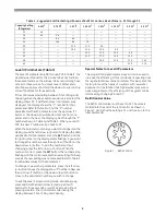
Table 9 - Regenerant Draw Value

Injector

Color

Regenerant Draw Value at:

30 psi

50 psi

70 psi

A

White

19

26

31

B

Blue

24

30

37

C

Red

29

37

40

D

Green

32

48

60

Summary of Contents for Autotrol Performa ProSoft 960 Series

Page 1: ...With 960 Series Control 5 Cycle Conditioner 5 Cycle FA Filter Water Conditioning Control System Installation Operation and Maintenance Manual Autotrol Performa ProSoft ...

Page 2: ... Regeneration Automatic Regeneration Performa 960 FA Control 12 Programming Level I Features Level II Features Manual Regeneration Automatic Regeneration Removing the Valve Assembly for Servicing 18 Preventive Maintenance 18 Injector Screen and Injector Water Meter Removing the Control 13 Specifications 21 Pressure Graphs 22 Identification of Control Valving 23 Valve Disc Principle of Operation 23...

Page 3: ...d fumes 7 The use of resin cleaners in an unvented area is not recommended Water Line Connection The installation of a bypass valve system is recommended to provide for occasions when the water conditioner must be bypassed for hard water or for servicing The most common bypass systems are the Autotrol Series 1265 bypass valve Figure 1 and plumbed in globe valves Figure 2 Though both are similar in...

Page 4: ...ere it could cause considerable damage This fitting should be on the side of the cabinet or regenerant tank To connect overflow locate hole on side of regenerant tank Insert overflow fitting not supplied into tank and tighten with plastic thumb nut and gasket as shown Figure 4 Attach length of 1 2 inch 1 3 cm I D tubing not supplied to fitting and run to drain Do not elevate overflow line higher t...

Page 5: ...rs of water to regenerant tank If the tank has a salt platform above the bottom of the tank add water until the level is approximately 1 inch 25 mm above the platform 5 Place the conditioner into operation A With the water supply valve completely open carefully advance the cycle indicator COUNTERCLOCKWISE to the center of the REFILL position Hold at this position until water starts to flow through...

Page 6: ...ess the SET button and the far right number on the display starts flashing If you want to change this number press the up arrow button to increase the number or the down arrow button to decrease the number To skip the number without changing press the left arrow button When you reach the far left digit pressing the left arrow button will return you to the far right digit Note If you press and hold...

Page 7: ...aining capacity below that number When water is flowing through the system the colon in the Time of Day display will blink At this time all of the mandatory parameters are filled and the control is ready for operation To further increase the efficiency of the system see P6 and P7 in the Level II Parameters Section The display will alternatebetween the Time of Day and Capacity if no keys are presse...

Page 8: ...ounds the new setting was not accepted Refer to Table 3 for allowable values for that parameter To change or view other parameters press the left arrow button to have the display show P numbers Now use the up arrow button or the down arrow button to move to the parameter number you wish to change To exit the Level II programming mode simultaneously press and hold the down arrow and up arrow button...

Page 9: ...clock Skip this parameter for a 12 hour clock or enter 1 for a 24 hour clock P14 Calendar override 0 to 30 1 0 Days 0 no calendar override Skip this parameter for no calendar override or enter a value P15 Reserve type 0 to 3 1 0 0 variable reserve 1 fixed reserve 2 variable reserve with immediate regen 3 fixed reserve with immediate regen Skip this parameter to accept the default or enter a differ...

Page 10: ...t Amount and Capacity values so they cannot be changed When Parameter 18 is set to 1 those two settings can only be viewed when the control is in the Level II mode The settings will be skipped when the control is in the Level I mode When Parameter 18 is set to zero the Salt Amount and Capacity can be viewed and changed in either Level I or Level II Parameter P19 is used at the factory to enter def...

Page 11: ... options for this control fixed reserve and historical water usage pattern They are selected with Parameter P15 Fixed Reserve When the fixed reserve is selected the control multiplies the maximum system capacity by the percent value set in Parameter P16 and uses the result as a reserve Water Usage Pattern The other reserve option allows the control to adjust the reserve based upon the historical w...

Page 12: ... the DOWN ARROW button displays the Level I Parameters in the following order Time of Day Time of Regeneration Factor A Regenerant Dosage Capacity If you continue to press the DOWN ARROW button the parameters start over with Time of Day Pressing the UP ARROW button displays the parameters in reverse order Refer to Table 5 for a description of these parameters and the available ranges for each para...

Page 13: ...on content Fe2 ________ppm Manganese content MN2 x 2 ________ppm H2S content x 4 ________ppm Total Demand ________ppm Example 4 0 ppm iron 4 0 ppm 3 0 ppm Manganese x 2 6 0 ppm 2 5 ppm H2S x 4 10 0 ppm Potassium Perm Demand 20 0 ppm Regenerant Dosage Regenerant dosage is the next value displayed Refer to Table 6 to find the correct regenerant dosage setting based on the volume of filter media and ...

Page 14: ...0 1 6 2 5 Gallons x 10 Liters x 10 Unit of measure depends on value selected for P12 Select regenerant dosage from Table 6 and enter that value P5 Capacity of Unit 0 1 to 140 0 0 01 to 14 00 0 1 0 01 1 0 0 1 PPM gallons PPM liters Unit of measure depends on value selected for P12 Enter the system capacity setting from Table 7 Table 6 Regenerant Dosage Settings gallons x 10 for Various Size Iron Fi...

Page 15: ...r clock 1 24 hour clock Skip this parameter for a 12 hour clock or enter 1 for a 24 hour clock P14 Calendar override 0 to 30 1 0 Days 0 no calendar override Skip this parameter for no calendar override or enter a value P15 Reserve type 0 to 3 1 0 0 variable reserve 1 fixed reserve 2 variable reserve with immediate regen 3 fixed reserve with immediate regen Skip this parameter to accept the default...

Page 16: ... and enter 46 Regenerant Draw Value Parameter P7 is used by the control to calculate the regenerant draw time The default value of 25 was selected for a B injector with low water pressure or an A injector with moderate water pressure If this does not match your installation press the SET button and enter a new value Refer to Table 9 for the correct value The injector cap is labeled with the inject...

Page 17: ...s the REGEN button This button is located on the front of the control When you press the REGEN button the control performs a full regeneration of the conditioner If you press this button again more than one minute after regeneration begins but before the regeneration is complete a second regeneration will start when the first regeneration is finished The display will freeze and only show the Regen...

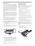
Page 18: ... 9 Figure 9 4 When used with a globe valve bypass loosen and detach the inlet outlet regenerant and drain lines from the valve If using the 1265 bypass loosen and remove valve from bypass as well as loosening and removing the regenerant and drain lines 5 Unscrew counterclockwise and remove valve from tank 6 To replace the control valve reverse the above procedure Preventive Maintenance Injector Sc...

Page 19: ...s into the bearing of the cage Reassemble the turbine cage and check that the wheel rotates freely 7 Reinstall the turbine cage into the outlet of the valve 8 Reinstall the pipe tube adapters or 1265 bypass to the inlet and outlet of the valve 9 Turn on the water supply or put the bypass valve s into the service position and purge the air out of the system To check for proper meter operation open ...

Page 20: ...he above procedure Note that the camshaft needs to be positioned correctly before it can be inserted into the back of the control There is a locating arrow on the camshaft Position the arrow on the top of the shaft and slide the camshaft into the control Push up on the end of the camshaft furthest from the timer snapping it into place Figure 15 ...

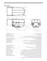
Page 21: ...nection 3 8 inch NPT male Drain Line Connection 3 4 inch NPT male Optional Bypass Valve Rotating handles full 1 inch porting reinforced Noryl Control Module Tank Adapter Reinforced Noryl Rubber Goods Compounded for cold water service Program Clock Timer 960 Available in English German French Italian Spanish Japanese Regenerant Refill Control 1 to 10 lbs 0 45 to 4 5 kg of salt or 3 to 19 lbs 1 4 to...

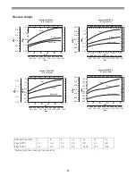
Page 22: ...C in a 268 Valve 20 40 60 80 100 120 400 600 800 1000 1200 1400 1600 1800 Brine Draw Rinse Total PSI bar M hr 3 GPM Injector 1031364 B in a 268 Valve 0 30 0 25 0 20 0 15 0 10 0 05 0 00 1 25 1 00 0 75 0 50 0 25 0 00 20 40 60 80 100 120 400 600 800 1000 1200 1400 1600 1800 PSI bar M hr 3 GPM Injector 1030272 D in a 268 Valve 0 30 0 25 0 20 0 15 0 10 0 05 0 00 2 25 2 00 1 75 1 50 1 25 1 00 0 75 0 50 ...

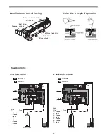
Page 23: ...d Water Soft Water 5 4 1 3 2 6 7 Backwash Flow Control 2 Backwash Position 1 Regenerant Valve 2 Bypass Valve 3 Inlet Valve 4 Outlet Valve 5 Refill Valve 6 Rinse Drain Valve 7 Backwash Drain Valves Flow Diagrams Valve No 1 Closed 2 Closed 3 Open 4 Open 5 Closed 6 Closed 7 Closed Valve No 1 Closed 2 Open 3 Closed 4 Open 5 Closed 6 Closed 7 Open 1 Service Position Valve Disc Principle of Operation ...

Page 24: ...5 4 1 3 2 6 7 Brine Adjustment Brine Tank Mineral Tank Drain Inlet Outlet Hard Water Soft Water 5 4 1 3 2 6 7 3 Brining Slow Rinse Position 4 Purge Position Valve No 1 Open 2 Open 3 Closed 4 Closed 5 Closed 6 Open 7 Closed Valve No 1 Closed 2 Open 3 Open 4 Closed 5 Closed 6 Open 7 Closed Valve No 1 Closed 2 Closed 3 Open 4 Open 5 Open 6 Closed 7 Closed 5 Regenerant Refill Position ...

Page 25: ...25 Replacement Parts 2 Performa Valve 3 4 14 9 1 5 6 10 11 7 8 12 12 13 15 ...

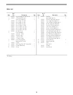
Page 26: ... 5 Lpm 1001615 25 mm CPVC Tube Adapter Kit 1000215 No 14 4 8 gpm 18 2 Lpm 1001769 3 4 inch NPT Plastic Pipe Adapter Kit 4 1030502 Ball Flow Control 1 1001603 1 inch NPT Plastic Pipe Adapter Kit 5 Injector Assembly 1 1001604 3 4 inch BSPT Plastic Pipe Adapter Kit 1032970 A Injector White 1001605 1 inch BSPT Plastic Pipe Adapter Kit 1032971 B Injector Blue 1001611 3 4 inch BSPT Brass Pipe Adapter Ki...

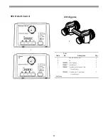
Page 27: ...cription Qty 1 960 ProSoft Control 1 2 FA 1 3 1040930 1265 Bypass 1 1000811 Transformer 1 1000907 Transformer Extension Cord 1 15 feet 4 6 m 1034264 Y Splitter run 2 units from 1 1 transformer 960 ProSoft Control Not Shown Performa ProSoft Performa FA ...

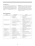
Page 28: ... controller to clean C Flush out foreign matter by holding disc open and manually operating valve stem D Check all connections in regenerant line for leaks Refer to instructions 3 System using more or less salt than salt control is set for A Inaccurate setting B Foreign matter in controller causing incorrect flow rates C Defective controller A Correct setting B Remove variable salt controller and ...

Page 29: ...en it should be closed Valve camshaft has been manually rotated out of regeneration complete position Faulty motor Faulty motor drive Faulty switch The control will turn the motor on and drive the camshaft to the proper location Replace the control Replace the control Replace the control Err4 Improper control settings one or more settings out of the allowable range One or more settings out of the ...

Page 30: ...ections H Remove foreign object obstruction from valve discs or camshaft I Install pressure regulator to reduce pressure J Replace control 10 Continuous regeneration Camshaft does not stop at the end of regeneration A Broken projection on drive gear B Defective switch A Replace control B Replace control 11 Control does not regenerate automatically or when REGEN button is depressed A Transformer un...

Page 31: ...hetic gel zeolite greensand and bentonites 5 25 Sodium Hypochlorite These solutions are available under trade names such as Clorox Bleach If stronger solutions are used such as those sold for commercial laundries adjust the dosage accordingly 1 Dosage A Polystyrene resin 1 2 fluid ounces per cubic foot B Non resinous exchangers 0 8 fluid ounce per cubic foot 2 Regenerant tank conditioners A Backwa...

Page 32: ... Copyright 2005 General Electric Company Printed in USA P N 1227756 Rev E ...

Reviews: