2
ATP2100 & ATP2600 Touchpads Installation Instructions
Mounting the Touchpad
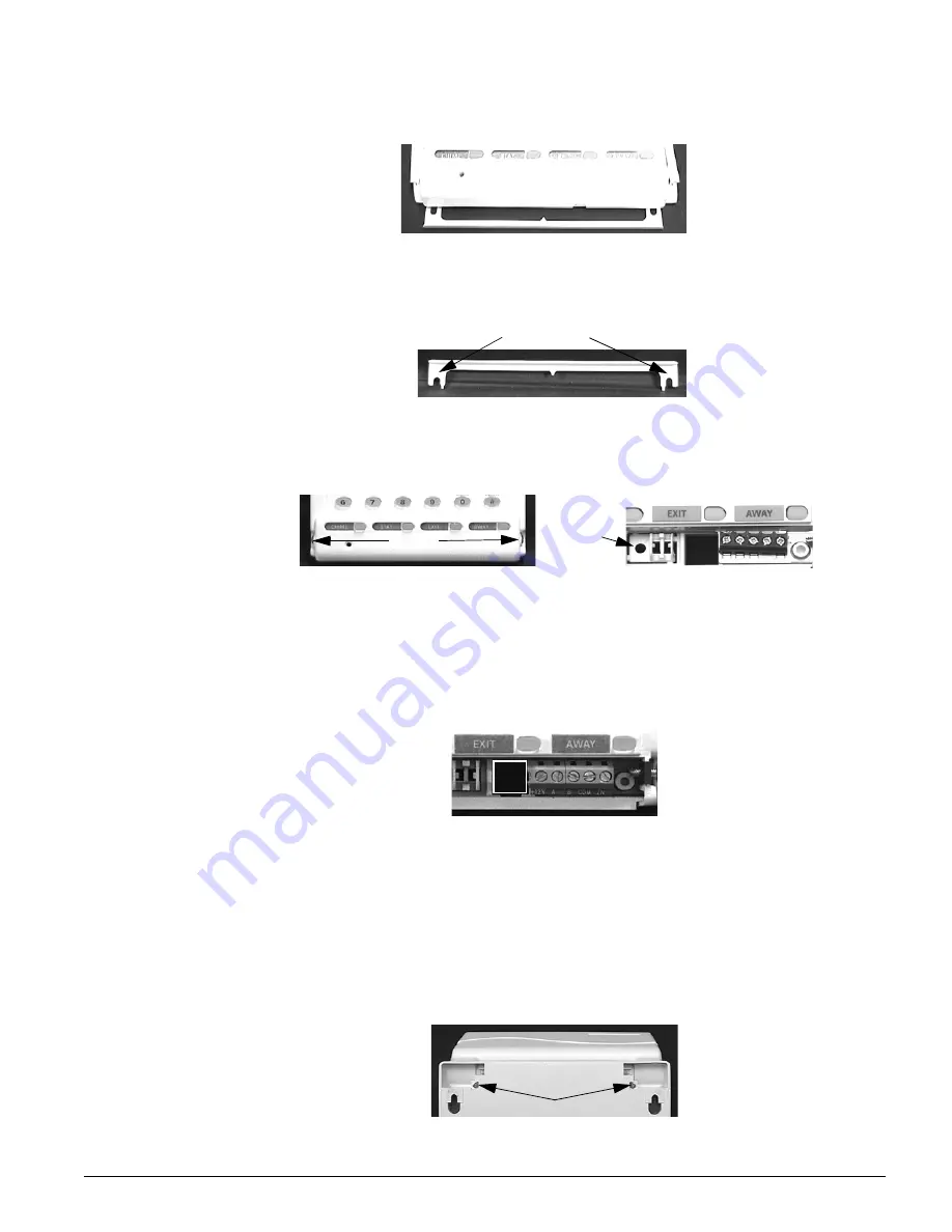
1. Remove the mounting template from the bottom of the touchpad (Figure 1).
Figure 1. Removing Mounting Template
2. Position the mounting template at the desired location and mark the mounting hole loca-
tions (Figure 2). You must allow at least 2-1/2 inches above it for the display.
Figure 2. Mounting Hole Locations
3. Loosen the lower side screws slightly to remove the lower cover, then mark the lower
mounting hole (Figure 3).
Note
On the model ATP2100, you must remove the door to access the lower side screws.
Figure 3. Removing Lower Cover to Access Lower Mounting Hole
4. Insert anchors into the wall at the marked locations where studs are not present.
5. Secure the mounting template using the screws provided, just so the template can be
removed with slight resistance.
6. With the template removed, align the mounting holes on the back of the touchpad with
the screws in the wall and slide the touchpad down.
7. Mark the area just left of the screw terminals (white outlined square in Figure 4). This is
where you need to route wiring to the touchpad.
Figure 4. Wire Access Area
8. Remove the touchpad from the wall and make a hole at the marked area.
9. Run a 4-conductor, 18- to 22-gauge wire from the panel to the touchpad (Table 2).
10. If using the hardwire contact input, run an additional 2-conductor, 22-gauge wire from
the contact location to the touchpad.
11. At the touchpad location, feed the wires through the wall and touchpad, then mount the
touchpad on the wall securing it with a screw at the lower mounting hole location.
Note
Before mounting the ATP2600, you may need to adjust the flip top movement to make sure it is not
too stiff or loose. Use the adjustment screws on the back of the touchpad (Figure 5), turning them
clockwise to stiffen movement or counterclockwise to ease movement.
Figure 5. Flip Top Adjustment Screws
Gently break off at each side.
Mounting Holes
Screws
Mounting
Hole


