background image

OUTDOOR TECHNICAL OVERVIEW

ENGLISH

Topic Title

B-18

Testing

Variable Speed Compressor

1. 

Begin by turning off power at the equipment disconnect switch. Adequate time must be given for capacitors on the circuit 

board to discharge. Wait a minimum of 12 minutes before handling the circuitry.

2.  Locate the Inverter control module (IPM). The IPM is connected to the main circuit board by a wire harnesses, and has the 

compressor connections mounted on it.

3.  Set your test meter to AC volts and test for voltage at the three compressor connections. Voltage should be zero before 

proceeding.

4.  Remove the three compressor connections making note of the terminal letter and the wire colors. 
5.  Set your ohm meter to the lowest resistance setting that is available. Test all three connections terminals using the following 

sequence:

•  U terminal to V terminal
•  U terminal to W terminal
•  V terminal to W terminal

All three resistance values should match the specification table below. Compressor windings are deemed bad if they are 
greater than 7% out of specification.  Readings taken at the wire IPM module that are outside of factory tolerances require 

steps 6 through 9.

6.  Remove the compressor blanket and set it aside. Remove the terminal block cover to expose the connections at the 

compressor terminals. Inspect for any visual damage. Remove all three wires from the terminals making note of the wire color 

and the terminal identifier.

7.  Repeat process outlined in step 5. Repair or replace the wires if the compressor windings check properly. 
8.  Check each terminal to ground (suction line connection at compressor) to check for grounded windings if the resistance 

values are not correct.

9. 

Replace the compressor if the winding measurements are greater than 7% out of specification.
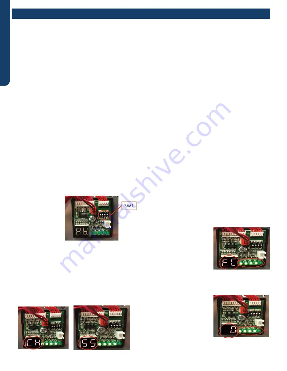
Wiring Error Check

1.  Disconnect power to 

the outdoor unit.

2.  Set Dip Switches 

SW1-1, SW1-2, 
SW1-3 & SW1-4 to 
the ON position.  
These dip switches 
are located on the 
Service Monitor 
Board.

3.  Turn ON power to the outdoor unit.
4.  All indoor fans will be set to HIGH fan speed.
5.  EEV for Circuit A will open. All other EEV’s will close.
6.  After a 3 minute delay, the Compressor will start and ramp 

up to 55HZ.

7.  The digital display with alternately display “CH” and 

“Compressor Frequency (HZ)” at 5 second intervals

8.  The system will circulate refrigerant through Circuit A for 

approximatley 10 minutes.

9.  Afterwards, Circuit A’s EEV will close and Circuit B’s EVV 

will open.

10. This process will be repeated for each indoor unit that is 

connected.

11. Once all indoor units have 

been checked, the digital 
display will display either 
“EC” or “0”. “EC” indicates 
a communication error 
between the outdoor and 
indoor unit. The LED(s) will 

be flashing, indicating which 

circuit has the fault

12. 

Once the wiring is corrected, re-run this test to confirm 

everything is functional.

13. “0” indicates that all wiring is 

correct.

14. If all wiring is correct, the 

LED’s remain solid lit.

15. Once the test is complete, 

make sure to change the dip 
switches back to the OFF 
position, and set each indoor 
unit to preferred set points.

Summary of Contents for ASH220NCDWA

Page 1: ...I 1 Outdoor ASH220NCDWA ASH324NCDWA ASH436NCDWA Indoor Wall Mount Highwall ASYW07URDWA ASYW09URDWA ASYW12URDWA ASYW18URDWA 2 x2 Compact Cassette AB09SC2VHA AB12SC2VHA AB18SC2VHA 3 x3 Large Cassette A...

Page 2: ...Oct 2020 Manual release Revision History...

Page 3: ...de A 6 Heat Mode A 7 Indoor Fan Control A 7 Cold Air Proof Operation A 7 Timing A 7 Indoor System Mode Conflict A 7 Abnormality Confirmation Approaches A 8 Low Load Protection Control A 8 High Load Pr...

Page 4: ...cal connections between the indoor and outdoor units Firmly clamp the interconnecting wires so they receive no external stresses Incomplete connections or clamping may cause terminal over heating or f...

Page 5: ...9000 20000 35 000 Max HeatingCapacity 15 FBtu hr 15000 16000 25 200 PowerSupply Voltage Cycle PhaseV Hz 208 230 60 1 208 230 60 1 208 230 60 1 WireSizebetweenIDandOD 14 4AWGStranded 14 4AWGStranded 14...

Page 6: ...AD07SL2VH AD09SL2VH AD12SL2VH AD18SL2VH Rated Cooling Capacity Btu hr 7 000 9 000 12 000 18 000 Rated Heating Capacity Btu hr 8 000 10 000 13 000 19 000 Voltage Cycle Phase V Hz 208 230 60 1 208 230 6...

Page 7: ...CoolingCapacityBtu hr 9 000 12 000 15 000 RatedHeatingCapacityBtu hr 10 000 13 000 18 000 Voltage Cycle PhaseV Hz 208 230 60 1 208 230 60 1 208 230 60 1 Airflow Turbo High Med Low Quiet CFM 264 235 20...

Page 8: ...he compressor will be stopped and the malfunction will be recorded in the malfunction list The indoor system will continue to run When the temperature of the indoor coil is raised to 45 F the compress...

Page 9: ...frosting finishes the coil malfunction will still be neglected until the compressor has been started up for 30 seconds The indoor temperature display will not change and the system operates at the col...

Page 10: ...d when the coil temperature is below 108 F and the system has been stopped for 3 minutes The malfunction will be stored in the malfunction resume and will not be revealed When the Compressor First Sta...

Page 11: ...sensor reads temperatures in excess of 131F Conditions that cause high indoor coil temperature include indoor fan failure dirty indoor coil and operating the system in heat mode when outdoor air tempe...

Page 12: ...This page intentionally left blank...

Page 13: ...Compressor Sump Heater B 11 Defrost Control B 12 Base Pan Heater Control Logic B 12 Troubleshooting the Base Pan Heater Error B 12 Discharge Sensor Protection B 12 High Current Protection B 13 High Pr...

Page 14: ...ll maintain individualized room temperatures as set on each controller provided all units are in the same mode If the first unit to be turned on is set to the heating mode all units will heat If the f...

Page 15: ...ration that could cause damage to the compressor windings IPM generates a large amount of heat during operation This heat is transfered to a heat sink behind the board then mixed with the outdoor air...

Page 16: ...monitor the temperature of the refrigerant entering and leaving each circuit These sensors are mounted in a group near the center of the circuit board There are system temperature sensors that monito...

Page 17: ...pacitors are fully charged the circuit opens to stop the charging process via the RL 2 relay The voltage between the two pins of CN 1 and the two pins of CN 2 is 12 VDC 2 2 6 4 4 3 3 5 1 1 The purpose...

Page 18: ...e compressor will discharge hot gas into the oil separator Oil will be trapped in the separator and returned to the suction inlet of the compressor via the capillary tube assembly low pressure path Co...

Page 19: ...perature of the refrigerant leaving the EEV The low pressure low temperature refrigerant will enter the mixed phase liquid line and travel to the indoor unit Heat from the indoor air passing across th...

Page 20: ...t will send the room temperature and set point requirement to the outdoor unit PCB via the data signal wire path The data travels from the indoor unit to the outdoor unit via the wire located on termi...

Page 21: ...id returning from the indoor coil The indoor EEV opening angle is fixed The liquid will enter the Liquid Line Strainer and will pass through the OPEN EEV The refrigerant liquid now enters a receiver w...

Page 22: ...osting FQY 80 Hz E 60s Soft startup Compressor 0HZ 0HZ 5s Outdoor motor ON Send defrosting signal to indoor Auto OFF 4 way valve ON OFF 15s 450 pulse 450 pulse 350 pulse E All EEVs Auto open angle Aut...

Page 23: ...uts off a 3 minute delay will occur before the 4 way valve is powered down and switches back to the at rest cooling position If the 4 way valve does not switch into the heating mode after 15 minutes o...

Page 24: ...bove 44 F 7 C for 60 seconds or is above 54 F 12 C for 30 seconds the defrost cycle will terminate If these temperatures cannot be reached the defrost cycle will automatically terminate in 10 minutes...

Page 25: ...5A 10A ASH324NCDWA 13 5 14A ASH436NCDWA High Pressure Protection in Cooling If there is an abnormal stop 3 times in 1 hour the unit will turn off Turn off and restore power to clear error Reduce FQY r...

Page 26: ...ions The first 8 minutes of run time when the compressor starts a new cycle During defrost When the ambient temperature is below 32 F 0 C Following the termination of an oil return cycle When any of t...

Page 27: ...Tc2AVE Max 10 minutes Oil Return in Heating Mode Oil Return Exit Conditions Heating Max 9 minutes E OR OR Td Tc for 30s continuously 5 minutes later begin to count Ts Tc2AVE for 30s continuously 5 min...

Page 28: ...te This is the feedback voltage to the PCB for determining the speed of the fan motor If the outdoor fan initially runs increases speed then stops and the Service Monitor Board indicates an error code...

Page 29: ...shorted the solenoid coil will have to be replaced 5 If the coil resistance is within the tolerance use a magnet along the valve body to determine the location of the piston If one end of the piston i...

Page 30: ...Repeat process outlined in step 5 Repair or replace the wires if the compressor windings check properly 8 Check each terminal to ground suction line connection at compressor to check for grounded wind...

Page 31: ...e Sensor Ts Compressor Suction Temp Sensor Ta Ambient Temp Sensor Td Compressor Discharge Temp Sensor Te Defrosting Temp Sensor Tm Module Temp Sensor Tc1 a b c d e Condensing Temp Sensor for Indoor Un...

Page 32: ...ture Sensor Ts Compressor Suction Temp Sensor Ta Ambient Temp Sensor Td Compressor Discharge Temp Sensor Te Defrosting Temp Sensor Tm Module Temp Sensor Tc1 a b c d e Condensing Temp Sensor for Indoor...

Page 33: ...tting without technical support 4 The LED1 LED5 in the service display board in turn corresponds to the communication status of ndoor unitA B C D LED will not lit if communication abnormal SW1 SW2 SW3...

Page 34: ...operation valid OFF Quiet operation invalid ON Note 1 Power input restrict selection OFF invalid ON valid 3500W 2 Quiet operation If OFF the outdoor unit will calculate and obtain the average ambient...

Page 35: ...heating ON OFF OFF OFF Forced cooling OFF ON OFF OFF Rated operation OFF OFF ON OFF Time defrost valid Defrost initiates if needed when the compressor has been on for 10 minutes continuously and 50 m...

Page 36: ...sensor failure Circuit B 34 Gas pipe sensor failure Circuit C 35 Gas pipe sensor failure Circuit D 36 Gas pipe sensor failure Circuit E 38 Malfunction of module temperature sensor momentary power fai...

Page 37: ...oor Wall Mount Unit Circuit Board C 3 Testing C 5 Accessing Components Removing Cover C 5 Indoor Fan Motor Voltage Check C 6 Replacing the Blower Motor C 6 Testing Temperature Sensors C 8 Testing Louv...

Page 38: ...ould the feedback signal not be present during a call for indoor blower the indoor control board will indicate a Malfunction Code E14 Louver Stepper Motors Separate motors located in the indoor unit c...

Page 39: ...ng functions of the indoor unit All control decisions are made by the outdoor unit ECU The indoor board has some limited diagnostic capability which will be covered in this manual Evaporator Coil Indo...

Page 40: ...s open The indoor unit temperature sensors are connected to the control board When testing the calibration of these sensors the wires can be released from the plug by pressing on the tension tab on th...

Page 41: ...d screws located near the bottom of the indoor unit These screws are located directly below the bottom of the air filter 4 Remove the filters 5 Manually open the louver 7 Remove the three screws locat...

Page 42: ...e indoor board is bad If voltage is present continue on 2 Check the voltage between Pins 3 and 4 The voltage should be 15VDC If it is not present the board is bad If voltage is present continue on 3 C...

Page 43: ...rator coil and remove the motor bracket 8 Loosen the motor shaft set screw Phillips head screw 9 Unplug the motor from the circuit board 10 Lift and slide the motor away from the blower wheel 11 Remov...

Page 44: ...oard is bad or the louver motor is defective It is more likely the motor is defective than the board Make sure the louver assembly is not binding and keeping the vanes from moving 1 Remove power from...

Page 45: ...WALL MOUNT TECHNICAL OVERVIEW ENGLISH Topic Title C 9 Wiring Diagrams...

Page 46: ...ndoor anti frosting protection F5 23 Module thermal overload F2 24 Compressor start failure over current F23 25 Phase current protection IPM F9 26 MCU reset F24 27 Module current detect circuit malfun...

Page 47: ...ting D 5 Accessing the Blower Motor and Condensate Pump D 5 Removing Fan Motor D 5 Removing Condensate Pump D 5 Indoor Fan Motor Test Procedure D 6 Testing Temperature Sensors D 6 Testing Louver Motor...

Page 48: ...These wires should always be 14 gauge AWG Stranded type wire Splices in wires 1 or 3 may cause communication errors Motor Blower The indoor unit features a multi speed blower motor that will change sp...

Page 49: ...motors are controlled by pulsed voltage that cannot be measured If the louver does not move when it should check for a bind in the louvers Piping Temperature Sensor The Piping Temperature Sensor sense...

Page 50: ...rd the Display Power Indicator will be lit The control board has a replaceable 3 15A 250V fuse that protects against excessive current If power is present at the board but the board does not work chec...

Page 51: ...condensate pump 3 Remove assembly 8 Slide condensate pan from cassette 2 Fan blade will slide off motor shaft 3 Remove Phillips head screw holding cover plate over motor wiring leads 4 Remove 3 nuts t...

Page 52: ...llowing 1 Confirm the sensor is firmly attached to the circuit board connection plug 2 Remove the sensor wires form the connection plug by releasing holding tension on the plugs tension tab 3 Use an o...

Page 53: ...ng 1 Remove power from the unit and remove the indoor unit cover 2 Access the circuit board 3 Identify the inoperable louver motor on the schematic drawing below and disconnect the plug from the circu...

Page 54: ...ive Perform the following test 1 Access the electrical control box 2 Unplug the float switch from the circuit board 3 The pump should start 4 If the pump does not start check for voltage at the pump c...

Page 55: ...1 29 BM1 1 BM1 7 BM1 8 TYPE DEFINE OFF OFF BM1 2 BM1 3 BTU B BLACK R RED W WHITE Y G YELLOW GREEN TEMP SENSOR ROOM SENSOR FLOAT SWITCH HEATER PUMP UP DOWN CN9 CN1 CN6 PANNEL CN4 CN11 CN19 CN13 CN3 ON...

Page 56: ...d 4 2 Indoor anti frosting protection 4 3 23 Module thermal overload 4 4 24 Compressor start failure over current 4 5 25 Phase current protection IPM 4 6 26 MCU reset 4 7 27 Module current detect circ...

Page 57: ...oard E 4 Testing E 5 Accessing the Blower Motor and Condensate Pump E 5 Removing Fan Motor E 5 Removing Condensate Pump E 5 Indoor Fan Motor Test Procedure E 6 Testing Temperature Sensors E 6 Testing...

Page 58: ...1 and 3 complete the data path These wires should always be 14 gauge AWG Stranded type wire Splices in wires 1 or 3 may cause communication errors Motor Blower The indoor unit features a multi speed...

Page 59: ...are controlled by pulsed voltage that cannot be measured If the louver does not move when it should check for a bind in the louvers Piping Temperature Sensor The Piping Temperature Sensor senses indoo...

Page 60: ...ine voltage to power the indoor unit comes in on Terminal Block connections 1 and 2 Power connects from these terminal connections to CH 3 and CH 4 on the circuit board If the board does not respond t...

Page 61: ...ndensate water from the pan by removing drain plug 10 Remove the screws holding on the condensate pan 2 Fan blade will slide off motor shaft 3 Remove Phillips head screw holding cover plate over motor...

Page 62: ...e following 1 Confirm the sensor is firmly attached to the circuit board connection plug 2 Remove the sensor wires form the connection plug by releasing holding tension on the plugs tension tab 3 Use...

Page 63: ...If the louver does not operate with command from the remote control either the indoor board is bad or the louver motor is defective It is more likely the motor is defective than the board Make sure t...

Page 64: ...form the following test 1 Access the electrical control box 2 Unplug the float switch from the circuit board 3 The pump should start 4 If the pump does not start check for voltage at the pump connecto...

Page 65: ...OLLER M SENSOR TEMP ROOM ROOM CARD CN3 CN6 T5A 250VAC CN16 DRAIN PUMP M CN9 CN10 CN4 CN14 FUSE FLOAT SWITCH CN13 CN4 CN3 CN2 CN7 CN1 CN6 INTELLIGENT MOVE EYE DEVICE M M LOUVER STEP MOTOR4 LOUVER STEP...

Page 66: ...default OFF Cooling only ON High performance cassette OFF OFF ON Indoor unit Address Indoor unit address for one wired controller control more than one unit BM3 5 BM3 6 BM3 7 BM3 8 0 master OFF OFF O...

Page 67: ...2B 23 Module thermal overload 4 4 2C 24 Compressor start failure over current 4 5 2D 25 Phase current protection IPM 4 6 2E 26 MCU reset 4 7 2F 27 Module current detect circuit malfunction 4 8 30 28...

Page 68: ...This page intentionally left blank...

Page 69: ...erview F 2 Indoor Unit Circuit Board F 3 Ductwork Grilles F 5 Testing F 6 Test Condensate Pump and Float Switch F 6 Testing Communication Circuit F 6 Testing Temperature Sensors F 7 Indoor Fan Motor V...

Page 70: ...remote control All operating status and information is displayed on the wired controller The Slim Duct unit does not have a display Slim Duct units are controlled by a wired controller only 8 8 6 4 4...

Page 71: ...ds to be pumped from the cassette The float switch connects onto the circuit board The float switch and pump are located behind the removable insulated cover next to the electrical control box The pum...

Page 72: ...or unit capacity Air Delivery Power is set with DIP Switches SW1 4 and SW1 5 The settings are shown in Hydrostatic Selection of 0Pa up to 30Pa SW1 7 and SW1 8 define the unit type The conversions are...

Page 73: ...ion Air distribution Air return blind Air return duct Indoor unit Rivet gluey nail heat preservation cotton tinfoil gluey nail cap adhesive tape Roof Installation Ceiling Air supply Unit Return air Re...

Page 74: ...es not start check for voltage at the control board pump connection There should be 230 Volts AC to the pump If there is not the circuit board is defective If there is proper voltage to the pump eithe...

Page 75: ...he air temperature near the sensor and compare the required resistance against measured resistance refer to charts in reference section If the sensor is within calibration the sensor is good If the se...

Page 76: ...DGE CN22 CN23 ON SLAVE UNITS PCB SHOULD BE CUT OFF WHEN ONE WIRED CONTROLLER CONTROL MORE THAN ONE UNIT OFF OFF SW1 4 SW1 5 SW1 6 OFF OFF OFF ON TEMP SENSOR ROOM SENSOR PIPING TEMP ROOMCARD CN13 CN19...

Page 77: ...Phase current protection IPM 4 6 26 MCU reset 4 7 27 Module current detect circuit malfunction 4 8 28 Liquid pipe sensor failure Circuit A 4 9 29 Liquid pipe sensor failure Circuit B 5 0 30 Liquid pi...

Page 78: ...This page intentionally left blank...

Page 79: ...6 Testing G 7 Test Condensate Pump and Associated Float Switch G 7 Testing Temperature Sensors G 7 Testing Communication Circuit G 8 Indoor Fan Motor Voltage Check G 8 Static Pressure Charts G 9 Boar...

Page 80: ...re accessed under the removable panel next to the electrical control box The wired controller can be configured to sense room air temperature There is no option for use with remote control All operati...

Page 81: ...ndensate pump The pump is connected to the circuit board The pump is energized whenever the Float Switch indicates that water needs to be pumped from the cassette The float switch connects onto the ci...

Page 82: ...ge From the ground connection at the Terminal Block to the Number 3 screw connection the voltage should pulse up and down when data is being transmitted Line voltage to power the indoor unit comes in...

Page 83: ...cycle will be active until one of the following occurs Fresh air function is canceled via the controller wired controller or wireless remote controller Indoor unit has been via the controller In Heati...

Page 84: ...n Air distribution Air return blind Air return duct Indoor unit Rivet gluey nail heat preservation cotton tinfoil gluey nail cap adhesive tape Roof Installation Ceiling Air supply Unit Return air Retu...

Page 85: ...Test Condensate Pump and Associated Float Switch If the internal condensate pump does not operate the pump may be bad or the float switch may be defective Perform the following test 1 Access the elec...

Page 86: ...and 23VDC The fluctuating signal indicates a good communication path 3 If the voltage does not fluctuate and the wiring is good the indoor board is defective If The Indoor Fan Motor Does Not Run 1 Rem...

Page 87: ...0 10 0 15 0 20 0 28 0 36 0 40 0 44 0 48 0 52 Air flow cfm Static pressure in wc AM09SL2VHA air flow and static pressure chart High cfm Med cfm Low cfm Quiet cfm USYM12UCDSA ENGLISH 350 0 400 0 450 0 5...

Page 88: ...ll connectors from the board 3 Remove the 2 board mounting screws and remove the board 2 Unplug the pump motor and float switch wires from within the air inlet 3 Remove the 4 screws holding the pump i...

Page 89: ...screws holding the blower housing to the unit 4 on each housing 8 Support the motor 2 people may be required at this time Loosen the 2 screws of the motor mount bracket and remove full assembly 9 Usi...

Page 90: ...witches setting without technical support 4 Get details from trouble shooting list about LED indication 5 Abbreviation RD red W withe BLK black BLU blue GRN green YL yellow Y G yellow green E A O exte...

Page 91: ...rm output ON Without filter clean warning OFF With filter clean warning ON North America area OFF Non North America area ON Description SW3 1 SW3 2 SW3 3 SW3 4 Special fresh air Canadian ventilation m...

Page 92: ...3 23 Module thermal overload 4 4 24 Compressor start failure over current 4 5 25 Phase current protection IPM 4 6 26 MCU reset 4 7 27 Module current detect circuit malfunction 4 8 28 Liquid pipe sens...

Page 93: ...Front Cover Removal H 4 Control Box Removal H 4 Board Replacement H 4 Upper Louver Removal H 5 Lower Damper Assembly Removal H 5 Replace Fan Motor H 5 Indoor Fan Motor Test Procedure H 6 Testing Tempe...

Page 94: ...nt Temperature Sensor senses room temperature This sensor provides room temperature information to the ECU for calculation of inverter capacity and temperature control WiFi Module Coil Sensor The Coil...

Page 95: ...power the indoor unit is made on terminal block connections 1 and 2 Power connects from these terminal connections to CH 3 and CH 4 on the circuit board If the board does not respond to command and ha...

Page 96: ...tal louver Lift up the top edge of the front cover and then pull forward Control Box Removal 1 Remove the screw from the right side of the box cover 2 Lift up the panel that contains the diagnostic po...

Page 97: ...te the bottom of the assembly outward Note When re installing the damper assembly first place the front edge of the condensate drain pan into place then rotate the bottom of the assembly into position...

Page 98: ...air cover and access the fan motor circuit board connection 3 Reset power and turn the remote control fan command to Fan On mode Motor Test 1 If the motor doesn t run check for 310VDC between Pins 1...

Page 99: ...reviation R red B black BL blue W white Y G yellow green TEMP temperature E A O exrernal alarm output Tr indoor unit room temperature sensor Tp indoor unit pipe temperature sensor coil temperature sen...

Page 100: ...it are correct There should no splices between the indoor and outdoor unit wiring connecting terminals 1 or 3 Make sure wiring is correct before performing this test 1 Measure the DC voltage between t...

Page 101: ...unit pipe temperature sensor coil temperature sensor Wire disp 07 upp Out 20 HEX Tp Tr SW1 1 OFF OFF SW1 2 OFF OFF OFF OFF OFF OFF OFF OFF OFF OFF OFF OFF OFF ON OFF OFF OFF OFF OFF OFF OFF ON SW1 3 S...

Page 102: ...F9 26 MCU reset F24 27 Module current detect circuit malfunction F10 28 Liquid pipe sensor failure Circuit A F16 29 Liquid pipe sensor failure Circuit B F17 30 Liquid pipe sensor failure Circuit C F1...

Page 103: ...Related to the IPM I 18 Error Codes Related to Compressor Outdoor Fan 4 Way Valve I 19 Flow Charts I 20 1 Outdoor EEPROM Malfunction I 20 2 Outdoor IPM over current or short circuit I 20 4 Communicat...

Page 104: ...This page intentionally left blank...

Page 105: ...es within 5 seconds You will hear 2 beeps as confirmation Forced Defrost This will force the unit to run a Defrost Cycle Wireless Controller Set the unit to HEAT 30 C and High fan speed Press the Slee...

Page 106: ...ess the ON OFF button on the remote control to save the changes Series IDU IDU PCB part number Controls Needed Guide Reference Haier GEA Controller IR Reciever Wired Controller 3X3 Cassette AL24LP2VHA...

Page 107: ...r from the indoor unit PCB 2 Apply power to the unit 3 Press the ON OFF button on the remote control HBS 01 4 Ignore this step if the display temperature is already O C Press MENU O F button to switch...

Page 108: ...A 18 18 36K D 18 24 42K A B 24 24 48K B C A x2 Three Zone 9 9 9 27K E 12 9 7 28K E 12 9 9 30K E 12 12 7 31K E 18 7 7 32K 12 12 9 33K E 18 9 7 34K 18 9 9 36K 12 12 12 36K E 18 12 7 37K 24 7 7 38K C A...

Page 109: ...22 11 33 26 521 592 18 73 4 23 10 86 25 283 563 66 75 2 24 10 42 24 111 536 65 77 25 10 00 23 511 08 78 8 26 9 60 21 947 486 94 F C Normal K 10K SENSORS 23K SENSORS 50K SENSORS 80 6 27 9 21 20 949 464...

Page 110: ...let Yellow Orange Red Blue 383 388 390 195 Violet 381 385 189 Yellow 388 193 Orange 196 Red EEV 6 pin 6 wire White Yellow Orange Blue Brown Red White OL 92 OL 46 OL Yellow OL 92 OL 46 Orange OL 46 OL...

Page 111: ...6 Vdc GND 1M 5 Blank Blank Blank 4 GND GND GND 3 Vcc GND 1M 2 Vsp GND 135K 1 FG GND 1M DC Fan Motor Pin Identification PIN Color Abbr Definition 1 Blue FG Revolution Pulse Output 2 Yellow Vsp Speed C...

Page 112: ...mbient temperature sensor Indoor heat exchanger temp sensor ASH220NCDWA ASH324NCDWA Comp ressor Discharge temp sensor Oil separator Capillary tube 2 7 1 0 1400 High pressure switch 4 way valve Pipe se...

Page 113: ...ceiver Liquid service valve 5 8 3 8 Unit A liquid pipe temp sensor Tc2 Strainer EEV A Indoor unit A Unit B liquid pipe temp sensorTc2 Strainer EEV B Indoor unit B Unit C liquid pipe temp sensor Tc2 St...

Page 114: ...nsor failure F6 F6 3 2 13 13 13 Discharge temperature sensor failure F25 F25 3 3 14 High outdoor suction temperature F30 F30 3 4 14 PFC circuit loop voltage 15 15 15 Communication failure between the...

Page 115: ...5 2 5 19 25 2 6 1A 2 6 2 6 2 6 1A 26 2 7 1B 2 7 2 7 2 7 1B 27 2 8 1C 2 8 2 8 2 8 1C 28 2 9 1D 2 9 2 9 2 9 1D 29 3 0 1E 3 0 3 0 3 0 1E 30 3 1 1F 3 1 3 1 3 1 1F 31 3 2 20 3 2 3 2 3 2 20 32 3 3 21 3 3 3...

Page 116: ...nsing temperature sensor F36 F36 5 9 40 Liquid pipe sensor failure Circuit E F33 F33 6 0 41 Toci temperature sensor failure F38 F38 6 1 42 42 High Pressure switch open F39 F39 6 2 43 43 Low Pressure s...

Page 117: ...35 53 5 4 36 5 4 5 4 5 4 36 54 5 5 37 5 5 5 5 5 5 37 55 5 6 38 5 6 5 6 5 6 38 56 39 57 5 7 39 5 7 5 7 5 7 39 57 5 8 3A 5 8 5 8 5 8 3A 58 5 9 3B 5 9 5 9 5 9 3B 59 6 0 3C 6 0 6 0 6 0 3C 60 6 1 3D 6 1 6...

Page 118: ...the calibration of the sensors The measured resistance must be within the tolerances located in the tables There are 16 potential Error Codes that can be generated by the PCB to indicate a failure of...

Page 119: ...Mode Overcharge Undersized refrigerant lines or excessive length Restriction Note If the refrigerant pressures are correct yet the system does not close the error reporting pressure switch replace th...

Page 120: ...Check the wiring and the connections CN9 on the PCB and CN15 on the IPM If the connections are good yet the boards do not communicate and the code will not clear check for correct voltage at the IPM...

Page 121: ...Possible Causes Overcharge Dirty outdoor coil Hot conditioned space temperature or high load Refrigeration circuit restriction Seized compressor Defective IPM Error Codes Related to Compressor Outdoor...

Page 122: ...causes EEPROM is bad Loose EEPROM wiring Correct the wiring Is electric box wiring correct and is compressor wiring firmly connected Is compressor normal compressor coil resistor insulation Is power m...

Page 123: ...e No The filter board is broken replace the filter board No 4 Communication abnormal between PCB and IPM Control board can not communicate with the compressor driver module for over 4 minutes Possible...

Page 124: ...ure over 115 C Error clears within 3 minutes if temperature lowers below 115 C Error status lock if it occurs 3 times in 1 hour Possible causes The sensor is bad or fixed bad The system is clogged The...

Page 125: ...he temperature acquired by PCB is not accurate Replace wire Is the communication wire is shorted Is the communication wire CN21 is disconnected Reconnect Reconnect Yes No No Yes Is the wiring connecti...

Page 126: ...n the 4 way valve No Replace 4 way valve Yes No Adjust the valve opening Yes Is the electronic expansion valve over throttled 17 4 way valve reversing failure Indoor pipe indoor ambient temperature Tm...

Page 127: ...ressor correct Is power module is normal Correct the wiring according to diagram Replace power module Yes Yes No No Compressor load too high find the reason Yes Is compressor is normal compressor coil...

Page 128: ...ower off Is pressure switch wiring connection ok Use multimeter to check the high pressure switch Is the switch short circuited Is the EEV coil wiring correct and firmly in place Is the stop valve is...

Page 129: ...ensor detection value is incorrect Refrigerant overcharge Blocked liquid line piping The outdoor unit cannot be turned on normally due to failure to open outdoor heat exchanger electronic expansion va...

Page 130: ...www geappliances com ductless GE Appliances A Haier Company Appliance Park Louisville KY 40225 2020 GE Appliances A Haier Company Issued Date 10 08 2020...

Reviews: