GE AKR-30S, Installation And Maintenance Instructions Manual
The GE AKR-30S is an advanced electrical circuit breaker designed for reliable performance. Ensure a smooth installation and effective maintenance with our comprehensive "Installation And Maintenance Instructions Manual". Download the manual for free at manualshive.com to access step-by-step guidance, enhancing your experience with this top-tier product.
Share
Download


Reviews:
No comments
Related manuals for AKR-30S

ADVAC
Brand: ABB Pages: 30

SACE Emax 2
Brand: ABB Pages: 60

SACE Tmax XT5
Brand: ABB Pages: 15

Power Break II
Brand: GE Pages: 2

Power Break II
Brand: GE Pages: 4

G Series
Brand: Eaton Pages: 2

520
Brand: Eaton Pages: 40

EntelliGuard G
Brand: GE Pages: 94

CH
Brand: Eaton Pages: 8

AK-2-15
Brand: GE Pages: 10

AK-1-15 Series
Brand: GE Pages: 7

VR Series
Brand: Eaton Pages: 8

Series NRX
Brand: Eaton Pages: 10

Series NRX
Brand: Eaton Pages: 15

L-PKZ0 Series
Brand: Eaton Pages: 2

IZM20
Brand: Eaton Pages: 8

IZM32
Brand: Eaton Pages: 60
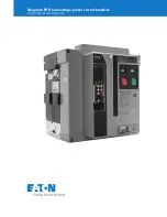
Magnum PXR
Brand: Eaton Pages: 68


