


OUTDOOR TECHNICAL OVERVIEW
ENGLISH
Topic Title
B-21
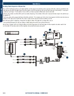
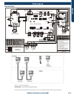
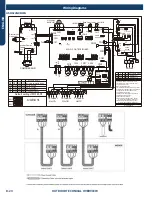
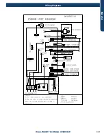
Wiring Diagrams
ASH436NCDWA
REFERENCE INF
ORMA
TION
PA
GE 112
ENGLISH
4U36EH2VHA
LP
H
P
CN9
GND
CN11
CON8
CN5
MAIN CONTROL BOARD
4-WAY
VALVE
DC FAN
MOTOR
250VAC T5A
FUSE
CON9
FG Vsp Vcc
ON
ON
Vdc
L1 L2
Power
supply
C
N
2
SW7
COMPRESSOR
CN15
CRANKCASE
HEATER
2
1
3
POWER FILTER
BOARD
P4
P2
P3
P1
ON
W
B
2
1
3
BL Y W B
R
G
Y/G
Y/G
R
ea
ct
or
L2
CN6
CN4
BL
BL
R
GRY
OR
OR
BASE PAN
HEATER
CN1 (
TC1)
CN24(
TC2)
E.E.V-O
E.E.V-A
E.E.V-B
E.E.V-C
DRIVE MODULE
P1
1
T20
A/
250
VA
C
COMM.
T
fin
L1
Tc
C
N
14
D
CN13
E.E.V-D
CN16
CN17
CN18
CN19
CN8
B
W
R
3
1 2
To Indoor
Unit A
3
1 2
CN23
CN21
ON
To Indoor
Unit B
To Indoor
Unit C
To Indoor
Ts
Ta
Td
T
e
C B A
D
C B A
LED2
SW6
SW5
U
V W
SERVICE
DISPLAY
BOARD
A B
CN
3
CN2
C
N
4
Sensor
abbreviation
:
Tc: Condensing Temp.
Ts: Compressor Suction
Temp.
Ta: Ambient Temp.
Td: Compressor Discharge
Te: Defrosting Temp.
Tfin: Module Temp.
TC1:Condensing Temp.
for Indoor Units A/B/C/D
Toci: Outdoor
Condensing inlet Temp.
Other abbreviation:
OR: Orange,Y/G:
Yellow/Green,W: White,
Y: Yellow, BR: Brown,
B: Black, BL: Blue,
GR:Green ,GRY:GREY
R: Red E.E.V:Electro
expansion valve,
LP/HP:
Low /high pressure switch
Note:
1.Dashed parts are
optional.
2.Please refer to
service manual to get
details of the DIP
switches .
3.Do not change the
DIP switches setting
without technical
support.
4.The LED1-LED5 in
the service display
board in turn
corresponds to the
communication status
of ndoor unitA,B,C,D.
LED will not lit if
communication
abnormal.
SW1 SW2 SW3 SW4
Start/+ Stop/-
FA
Y/G
R
EA
R
TH
L1
L2
L1
’
(Gas Pipe)
TC2:Condensing Temp.
for Indoor Units A/B/C/D
(Liquid Pipe)
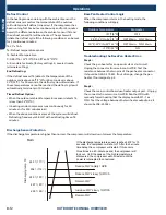
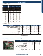
Definition of Dispaly board SW1
SW1-1 SW1-2 SW1-3
SW1-4
Normal Operating(default)
OFF OFF OFF OFF
ON OFF OFF OFF
OFF ON OFF OFF
OFF OFF ON OFF
Manually forced Heating
Manually forced Cooling
Rated Operating
(
fixed speed
)
OFF OFF
ON
OFF
Time Defrost Valid
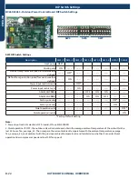
4U36EH2VHA1
SW5
1 2 3 4 5 6 7 8
ON
SW7
1 2 3 4 5 6 7 8
ON
Factory defaultof main control board SW5 & SW7
Unit D
Remote
central
A
B
controller
0150538688
0150538688
LED1
GR
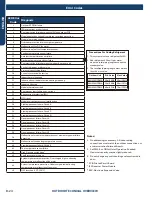
Other detail s about the service information please please refer to technical service mannual.
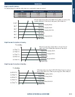
Centralized control address
SW6-1 SW6-2 SW6-3
SW6-4
OFF OFF OFF OFF
Definition of main control board SW6
Indoor unit address group1
( NO.1-NO.5) (default)
ON OFF OFF OFF
Indoor unit address group2
( NO.6-NO.10)
……
ON ON ON ON
Indoor unit address group
16( NO.76-NO.80)
R
W
B
B
W
W
5V(V+)
COM
GND
Toci
B
BL
W
C
N
7
W
R
R
Y
GR
BL
W
W
W
pin1
W
R
R
R
R
R
R
W
A
B
C
D
ON ON ON ON IDU&ODU Wiring Error Check
C1 C2
R
W
GR
W
MAIN side pin1-DISPLAY side pin5
pin1
SW1
B
W
B
B
W
W
B
LED5
SMG1
ON
ON
Means switch at ON position
Means switch at OFF position
R W B
pin1
pin1
pin1
W
B
W
B
B
ACL(L1)
ACL(L2)
CN12
R
Y
L2
’
T20
A/
250
VA
C
LED4 LED3 LED2 LED1
FAN
Summary of Contents for AB09SC2VHA
Page 2: ...Oct 2020 Manual release Revision History ...
Page 12: ... This page intentionally left blank ...
Page 45: ...WALL MOUNT TECHNICAL OVERVIEW ENGLISH Topic Title C 9 Wiring Diagrams ...
Page 68: ... This page intentionally left blank ...
Page 78: ... This page intentionally left blank ...


