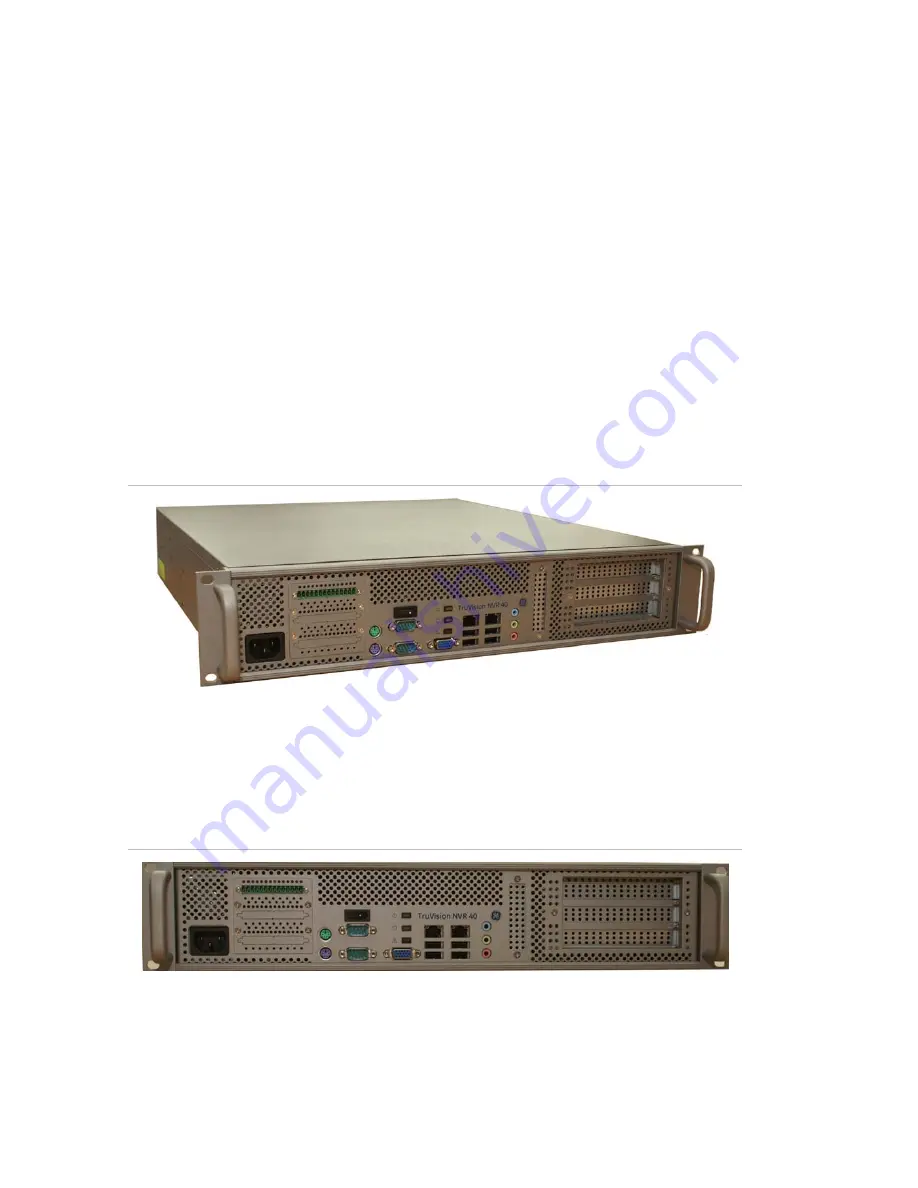
TruVision NVR 40 unit overview
8
TruVision NVR 40 User Manual
Before you begin
Inspect the package and contents for visible damage. If any components are
damaged or missing, do not use the unit; contact the supplier immediately. If you
need to return the unit, you must ship it in the original box.
Refer to the “Site Preparation and Safety Guidelines” on page 5 for more information
on safety measures necessary in order to perform any operation using the TruVision
NVR 40.
References and related documentation
• Centralized Configuration Server user manual
• VisioWave Security Center user manual
TruVision NVR 40 network video recorder
Figure 1: TruVision NVR 40 unit
Physical description
The TruVision NVR 40 unit is a 2U high enclosure for 19’ rack mounting.
TruVision NVR 40 front panel
Figure 2: TruVision NVR 40 front panel
The TruVision NVR 40 unit has all its connectors on the front panel. All functions are
thus accessible via the front panel. This includes all interface modules, start button,
and all the connectors. For an exhaustive list of connectors, see Figure 7 on page 14
and section “Front panel connectors” on page 14.


