background image


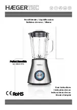
PARTS 


1.


Die cast base 

2.


Control panel (see detail) 

3.


Jar collar 

4.


Blade assembly 

5.


Glass blending jar 

6.


Jar lid 

7.


Measuring cap 

8.


Cord storage (bottom of base) 


Exploded view of glass jar 

12.


Glass blending jar 

13.


Jar collar 

14.


Silicone sealing ring 

15.


Blade assembly  

16.


Black locking ring 


On control panel 

9.    Speed selector (0-3 and crush) 
10.  Power indicator light 
11.  Pulse button 
 

9. 

10. 

11. 

12. 

16. 

15. 

14. 

13. 

1. 

2. 

3. 

6. 

7. 

5. 

4. 

Summary of Contents for 169106

Page 1: ...7 556 0973 Canada Thank you for purchasing a GE small appliance In keeping with the GE ecomagination initiative please consider the option to recycle the packaging material and donate the appliance you are no longer using To read about GE s ecomagination commitment visit http ge ecomagination com ...

Page 2: ... reduce the risk of injury never place cutter assembly blades on base without jar properly attached Always operate blender with cover in place When blending hot liquids remove center piece of two piece cover Do not place on or near hot gas or electric burner or in a heated oven To disconnect turn the control to off then remove plug from wall outlet Do not use appliance for other than intended use ...

Page 3: ... grounding plug to a 2 ground receptacle The grounding tab which extends from the adaptor must be connected to a permanent ground such as a properly grounded outlet box as shown in Figure C using a metal screw LINE CORD SAFETY TIPS 1 Never pull or yank on cord or the appliance 2 To insert plug grasp it firmly and guide it into outlet 3 To disconnect appliance grasp plug and remove it from outlet 4...

Page 4: ...ar lid 7 Measuring cap 8 Cord storage bottom of base Exploded view of glass jar 12 Glass blending jar 13 Jar collar 14 Silicone sealing ring 15 Blade assembly 16 Black locking ring On control panel 9 Speed selector 0 3 and crush 10 Power indicator light 11 Pulse button 9 10 11 12 16 15 14 13 1 2 3 6 7 5 4 ...

Page 5: ...5 OPERATING INSTRUCTIONS Blending Cleaning and Storage 1 2 3 4 5 6 7 8 9 10 11 ...

Page 6: ...clockwise until it is tightened see figure 10 Note If you notice liquid leaking at the bottom of the glass blending jar remove the black locking ring and re tighten it Blending 1 Before starting make sure the blender is in the off position The off position is when the blue indicator dot on the speed selector knob aligns with the 0 marking 2 Add ingredients to the blending jar see figure 1 3 Place ...

Page 7: ...brush to clean the glass jar 3 Do not use scouring pads or harsh chemicals on any plastic or metal parts 4 Do not fill the jar with boiling water Do not place any parts in boiling water 5 Do not allow the blade assembly to soak in water for long periods of time To Disassemble the Blade Assembly For Cleaning 1 Remove the glass blending jar from the die cast base and turn it over 2 Rotate the black ...

Page 8: ...8 ...

Reviews: