


3 | GE Oil & Gas
© 2015 General Electric Company. All rights reserved.
5. Body Disassembly (Refer to Figure 9)
Access to the internal components of the body should be
accomplished with the actuator removed. To remove the actuator
from the body, refer to the appropriate actuator instruction
GEA19530.
Prior to performing maintenance on the valve, isolate the valve,
vent the process pressure, shut off supply and signal air lines to
the actuator. In addition, it is recommended that the bonnet, body
and bottom flange be marked in relation to each other so the same
orientation can be maintained during reassembly.
A. Remove stem lock nuts and travel indicator if applicable.
B. Remove packing flanged nuts (2), packing flange (3), packing
follower (19) from the bonnet.
C. Remove body stud nuts (11) from around the bonnet and bottom
flange.
D. Remove bonnet (6) bottom flange (10) gaskets (13) and plug and
stem subassembly (9, 1 and 8) from the body.
Note: If a new body gasket (13) is not available, care must be taken
to preserve the old gasket for reuse. Spiral wound flexitallic gaskets
are standard in the 10000 Series design, and it is recommended
that a new gasket be installed each time the valve is disassembled.
E. Remove packing (17) and packing spacer (18) from the bonnet.
F. Inspect all parts for wear and service damage. If bushings (14) must
be removed from the bonnet or bottom flange, refer to Section
6.2. After determining the maintenance required, proceed to the
appropriate section of these instructions.
6. Maintenance / Repair
The purpose of this section is to assist maintenance personnel by
suggesting methods of component maintenance which is largely
dependent on the tools and machine shop equipment available.
Each section should be read and understood before proceeding.
6.1 Seat Ring Removal
Threaded seat rings (15 and 16) are installed tightly at the point of
manufacture and after years of service they are often difficult to
remove. To facilitate removal, seat ring wrenches can be fabricated
to engage the seat ring lugs and adapted to a shock wrench
(see Figure 3). If the ring is exceptionally resistant to removal the
application of heat or penetrating oil should be helpful.
Figure 3
When using heating devices, ensure that proper safety practices are
observed. Such items as flammability and toxicity of the controlled
substance must be considered and proper precautions taken.
6.2 Bushing Removal
The bushings (14) are press fit into the bonnet and bottom
flange, and do not normally require replacement. However, should
replacement be required, they can be pulled or machined out.
When machining the bushings out, care must be taken to maintain
proper dimensions and tolerances. These will be furnished upon
request.
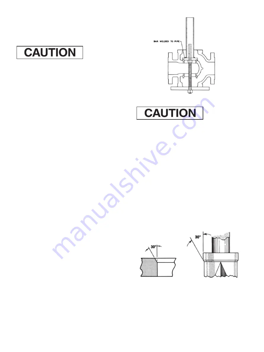
6.3 Lapping Seats
Lapping is the process of working the valve plug against the seat
ring with an abrasive to produce a close fit. When valve leakage
becomes excessive, lapping becomes necessary.
The plug and seat ring seating surfaces should be free of large
dents, scratches and the contact surfaces of the seats should be as
narrow as possible. This may require dressing both parts in a lathe.
Both surfaces make an angle of 30˚ with the axis of the plug (see
Figure 4).
Figure 4
For the lapping operation, a good grade of fine grinding compound
is required. The compound would be mixed with a small quantity
of lubricant, such as graphite. This will slow the cutting rate and
prevent tearing of the seating surfaces. The amount of lapping
required depends on the materials, condition of seating surfaces
and accuracy of machining. If a short period of lapping does not
visibly improve seating there is usually no advantage in continuing,
as too much lapping may result in rough seats. The only remedy is