


Quick Start 22
LOGIQ
500 Quick Start Guide
2276613–100 Rev. 0
Doppler Controls (cont’d)
HPRF—Allows the operator to enable or disable the High Pulse
Repetition Frequency function while in Doppler Mode. Not available in
the CWD Soft-Menu.
Rejectn—Allows for the elimination of low level echoes from the display.
CFM/PWD Ratio—Used to set the velocity ratio between PWD and
CFM. Active in triplex mode. Not available in the CWD Soft-Menu.
CFM Shrink—Reduces the CFM window to specified size. Not available
in the CWD Soft-Menu.
Realtim Trace—Automatically traces in real-time.
Calc Dir.—Choose which part of the Doppler Trace is used for automatic
measurements/calculations.
Trace Method—Choose the method used to trace the Doppler
waveform in real-time (Peak, Floor, Mean or Mode).
Dynamic Range—Controls how echo intensities are converted to
shades of gray, thereby creating a range of gray scale that can be
adjusted.
40
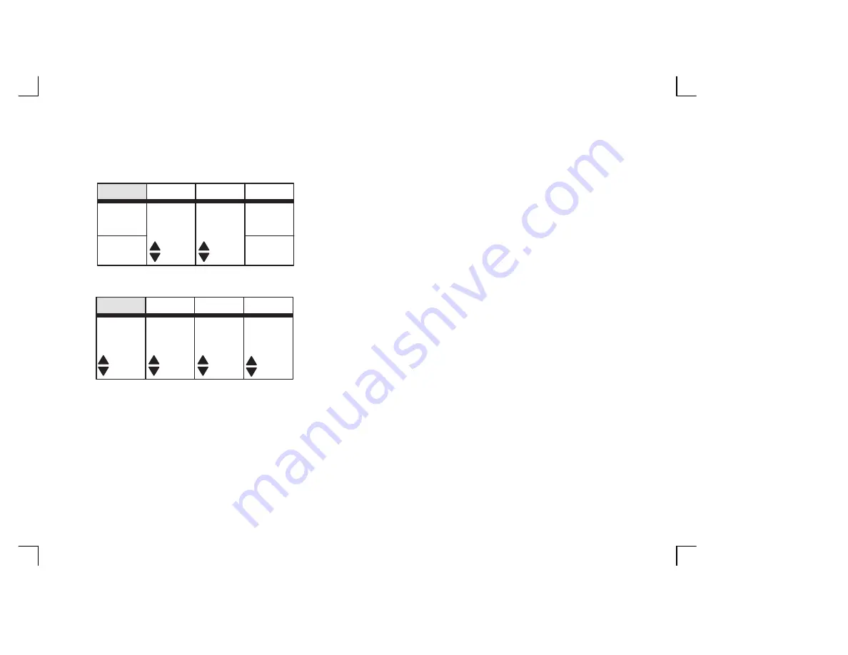
Preset
PWD
CFM
Shrink
CFM/PWD
Ratio
Rejectn
HPRF
Set Up
ECG
1/2
Compo
Preset
PWD
Trace
Method
Calc
Dir.
Realtim
Trace
Set Up
ECG
PEAK
OFF
Dynamic
Range
30