


10
11
As a result of continuous improvement and further development of our designs, the information and illustrations in this brochure are not binding.
The specifications and installation lengths of the machine manufacturer must be observed. All specifications are in mm. Errors and omissions excepted.
GDS
SHARK basic safety instructions
GDS
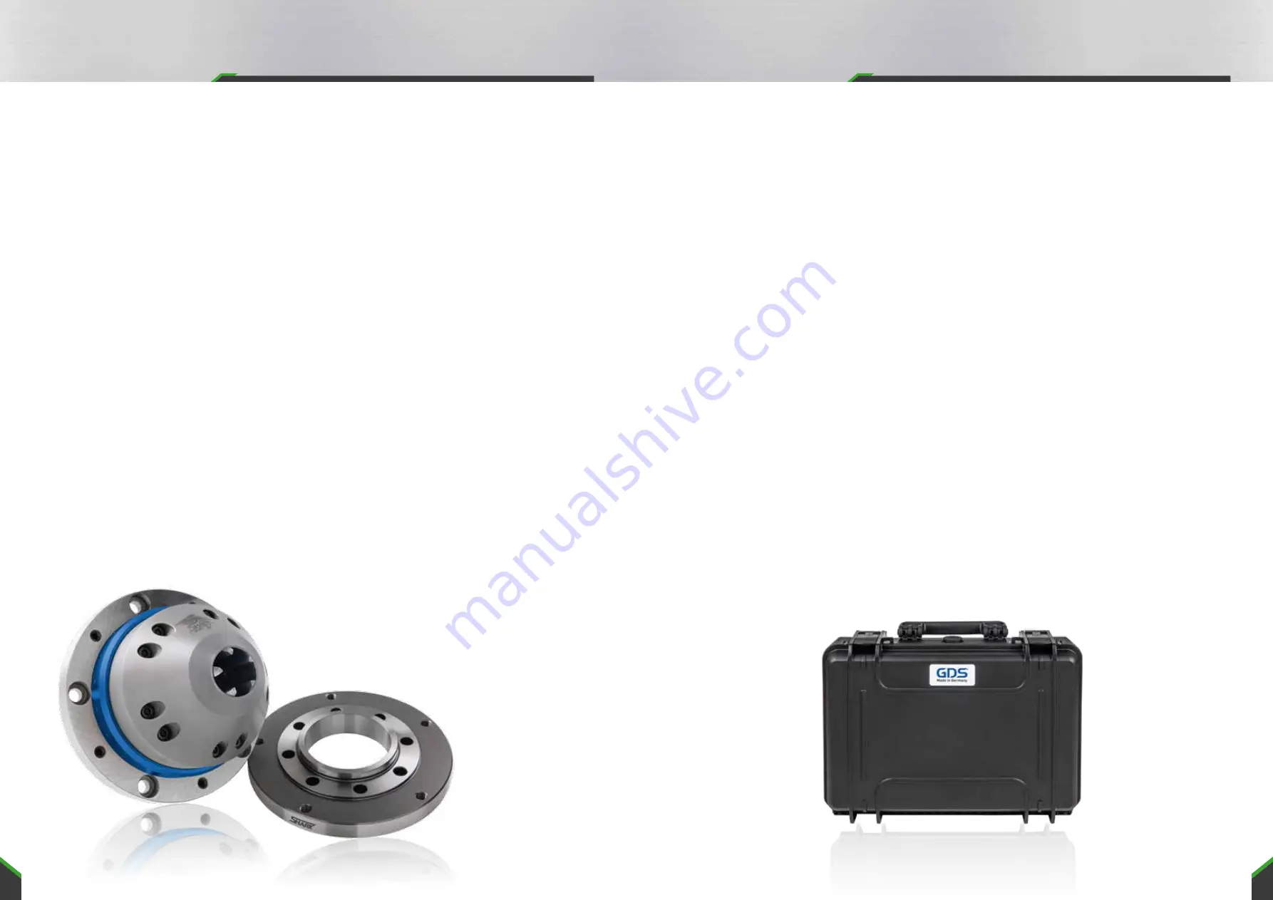
SHARK Aufbau
Note for safe operation
•
Cylindrical tools with an outer diameter of at least 3 mm can be clamped as the smallest tool. If
smaller tools are clamped, they cannot be clamped safely.
•
With manual loading, there is a risk that limbs can be trapped and crushed. Therefore, an inser-
tion aid must be used for manual loading.
•
Out-of-round tools damage the 5-jaw chuck or have an unfavorable effect on the grinding accu-
racy. The concentricity of the tools must not exceed 0.006 mm.
•
The chuck must not be used in EDM machines. Corrosion can cause the 5-jaw chuck to lose its
specification.
•
Observe the maintenance and care instructions.
Function test
After the 5-jaw chuck has been set up, its function must be checked by commissioning. If the
clamping device is changed, it is necessary to adjust the 5-jaw chuck to the new situation with a
new stroke check.
Structure of the 5-jaw chuck
The 5-jaw chuck and the associated actuating device must be matched to each other. The stroke of
the chuck must be sufficient to safely accommodate the largest and smallest diameter to be clamped.
When mounting the chuck and the clamping cylinder on the grinding machines, the following safety
requirements must be observed:
•
The machine spindle must not start until the clamping pressure is built up in the clamping cy-
linder and the clamping takes place in the permissible working range and the machine door is
closed.
•
It must not be possible to release the tension until the machine spindle has come to a standstill.
•
If the clamping energy fails, the tool must remain firmly clamped until the spindle comes to a
standstill.
•
In the event of power failure and return, there must be no change in the current switching posi-
tion.
•
The axial movement of the drive cylinder must not exceed a speed of 10 mm/sec when loaded
manually.
Clamping depth
The clamping depth depends on the clamping diameter.
The minimum clamping depth for optimum concentricity is 2.5 x D clamping diameter.
Adjusting the clamping range
You can set the desired clamping range by adjusting the adjusting screw (see page 6 step 6).