background image

5. INSTALLATION OF ENTERPRISE STORAGE/ ENTERPRISE STORAGE PLUS 


INSTALLATION MANUAL FOR LPU-1000 LED PLAYER UNIT 

-45-  

26 Feb 2018 


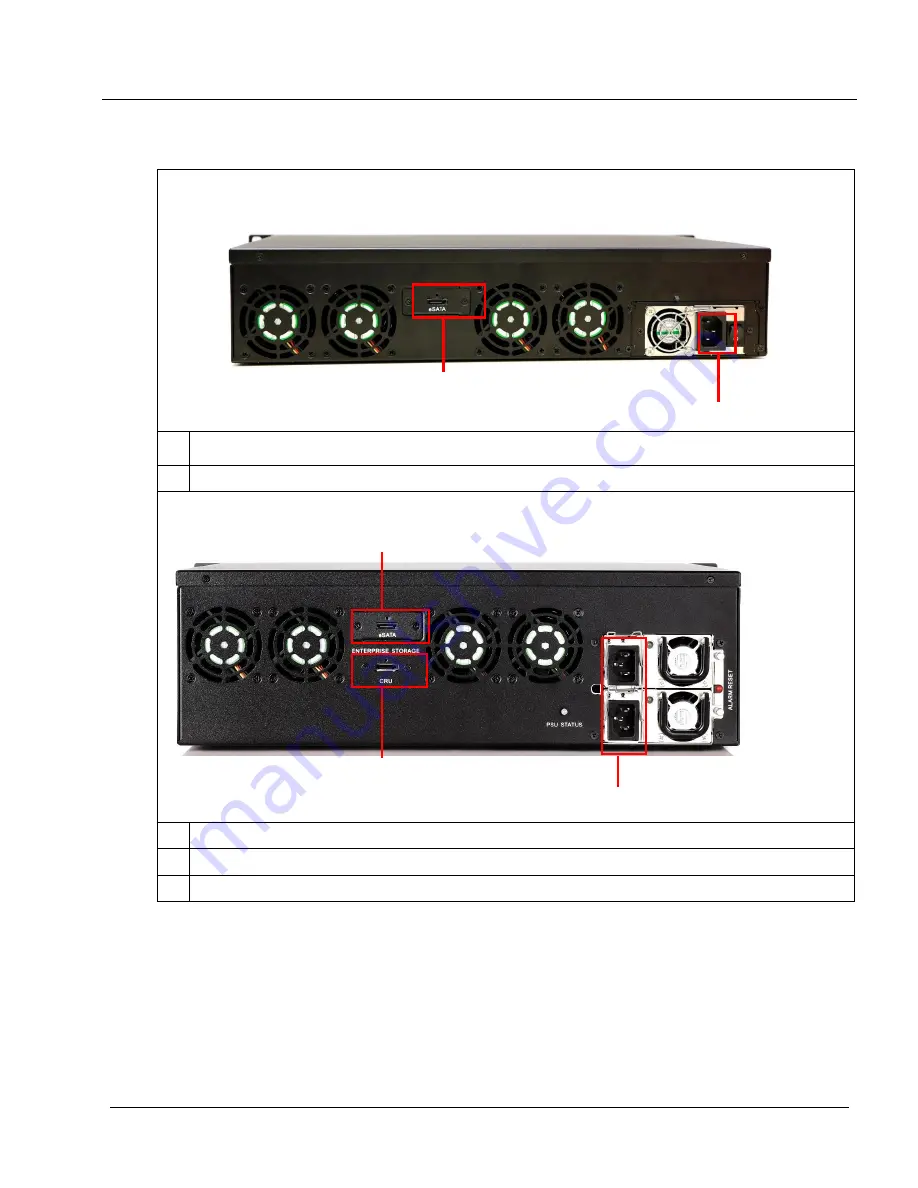
5.4 Back Panel 


Enterprise Storage


Power Connector 

eSATA Connector 

Enterprise Storage Plus


Power Connector 

eSATA Connector 

CRU Connector 


Important Note:

 Always power on the Enterprise Storage/Enterprise Storage Plus before powering up the LED Player Unit. 


Summary of Contents for LPU-1000

Page 1: ...UAL FOR LPU 1000 LED PLAYER UNIT THIS DOCUMENT IS PROPRIETARY AND CONFIDENTIAL NO PART OF THIS DOCUMENT MAY BE DISCLOSED IN ANY MANNER TO A THIRD PARTY WITHOUT THE PRIOR WRITTEN CONSENT OF GDC TECHNOL...

Page 2: ...1 Assembly of the LED Player Unit 33 3 2 Cable Connection with the LED Player Unit 37 3 3 Installation of the LED Player Unit Cover 40 3 4 Power Cord Connection to the LED Player Unit 42 4 External M...

Page 3: ...up 63 11 1 Configuring a content ingest source 63 11 1 1 Content ingest from USB disk 63 11 1 2 Content ingest from FTP 64 11 2 Selecting an ingest source 64 12 Audio Setup 65 13 Subtitles 67 14 Autom...

Page 4: ...in a retrieval system or translated into any human or computer language in a form or by any means electronic mechanical photocopying recording magnetic optical manual or otherwise or disclosed to thir...

Page 5: ...en China Tel 86 755 8608 6000 C Esteve Terradas n 27 esc D Despacho 1 08023 Barcelona Spain Tel 34 93 159 51 75 Peru Lima USA Los Angeles Brazil S o Paulo Singapore Calle Manuel Miota 170 Miraflores L...

Page 6: ...rat 11440 Tel 62 21 2920 4691 3F Kyobashi Chuo Bldg 1 14 7 Kyobashi Chuo ku Tokyo 104 0031 Japan Tel 81 3 5524 2607 Office No B 207 208 Everest Chamber Andheri Kurla Road Marol Andheri East Mumbai 400...

Page 7: ...ed for the installation The LPU 1000 LED Player Unit Packaging includes Item Qty Photo for reference only Media Block with Supporting Coverplate 1 RJ45 AES Audio Cable 1 RJ45 GPIO Cables 2 Power Cord...

Page 8: ...2018 The Enterprise Storage Packaging Includes Item Qty Photo for reference only Enterprise Storage 1 HDD Tray Key 1 3 5 SATA HDD 5 Power Cord 1 eSATA Cable 1 Manual CD 1 Quick Start Guide 1 The numb...

Page 9: ...erforming visual physical check of the LED Player Unit 1 Perform visual check of the physical appearance of the LED Player Unit If there are any damages deformities or other problems please contact th...

Page 10: ...cover by unscrewing the 6 screws as circled below 4 Hold the center position of the cover Remove the cover and set it aside 5 Perform visual check of the components and cabling in the LED Player Unit...

Page 11: ...o below shows the components and cabling available in the LED Player Unit Touch Panel Sub board Power Supply Unit Lower T Con Tamper Switch Fan Fan Cable Fan Fan Cable 8 Pin Power Slot Upper T Con LED...

Page 12: ...LAYER UNIT INSTALLATION MANUAL FOR LPU 1000 LED PLAYER UNIT 12 26 Feb 2018 2 2 Disassembly of the LED Cinema Processor Board To install the media block the LED Cinema Processor Board needs to be disas...

Page 13: ...BLOCK IN THE LED PLAYER UNIT INSTALLATION MANUAL FOR LPU 1000 LED PLAYER UNIT 13 26 Feb 2018 1 Disconnect all five cables around LED Cinema Processor Board a Disconnect the fan cables on both sides by...

Page 14: ...IA BLOCK IN THE LED PLAYER UNIT INSTALLATION MANUAL FOR LPU 1000 LED PLAYER UNIT 14 26 Feb 2018 b Disconnect the tamper switch cable by pressing the cable slot c Disconnect the 8 pin power cable by pr...

Page 15: ...OCK IN THE LED PLAYER UNIT INSTALLATION MANUAL FOR LPU 1000 LED PLAYER UNIT 15 26 Feb 2018 d To disconnect the FFC cable lift the metal lock and then pull out the cable Lift the metal lock up Pull out...

Page 16: ...2 ASSEMBLY OF THE MEDIA BLOCK IN THE LED PLAYER UNIT INSTALLATION MANUAL FOR LPU 1000 LED PLAYER UNIT 16 26 Feb 2018 2 Unscrew the 6 screws on the LED Cinema Processor Board...

Page 17: ...R UNIT INSTALLATION MANUAL FOR LPU 1000 LED PLAYER UNIT 17 26 Feb 2018 3 After unscrewing the screws hold the center position of the LED Cinema Processor Board take it out and set it aside Handle with...

Page 18: ...k 2 3 1 Disassembly of the Media Block supporting coverplate 1 The media block is delivered with a supporting coverplate indicated below which is required for support in the box during shipment 2 Sinc...

Page 19: ...e screws and rings are removed and set aside for installation in Section 2 3 2 step 8 Important note Please keep the media block supporting coverplate after the installation even if it is not in use T...

Page 20: ...e Media Block 1 Remove the media block supporting metal stand by unscrewing the two screws indicated below 2 Put the supporting metal stand at the back of the media block Install by screwing in the in...

Page 21: ...LED PLAYER UNIT 21 26 Feb 2018 3 Hold the center part of the media block as shown in the photo Remarks When handling the media block put on anti static wristband or anti static gloves 4 Insert the me...

Page 22: ...UNIT INSTALLATION MANUAL FOR LPU 1000 LED PLAYER UNIT 22 26 Feb 2018 Hold the back part of the media block and the supporting metal stand under it then insert it gently Check and make sure the media b...

Page 23: ...T 23 26 Feb 2018 Also follow the photo below for the installation direction of VGA connector with the longer side facing downward The photo shows the correct installation with the coverplate 5 After i...

Page 24: ...OR LPU 1000 LED PLAYER UNIT 24 26 Feb 2018 6 Screw in the media block together with the earth ground cables at indicated positions below Remark The photo is for reference only The number and installat...

Page 25: ...LY OF THE MEDIA BLOCK IN THE LED PLAYER UNIT INSTALLATION MANUAL FOR LPU 1000 LED PLAYER UNIT 25 26 Feb 2018 7 Screw the rings according to the indicated positions below 8 Screw in the supporting meta...

Page 26: ...he LED Cinema Processor Board 1 Flip the FFC cable upwards and leave space for the LED Cinema Processor Board 2 Hold the center part of the LED Cinema Processor Board as shown in the photo Insert the...

Page 27: ...LOCK IN THE LED PLAYER UNIT INSTALLATION MANUAL FOR LPU 1000 LED PLAYER UNIT 27 26 Feb 2018 3 Check and make sure the screwing openings position on the media block and LED Cinema Processor Board match...

Page 28: ...R LPU 1000 LED PLAYER UNIT 28 26 Feb 2018 4 When screwing in the LED Cinema board first screw in the 6 screws for fixing its position then tighten the screws in the direction of S shape as indicated b...

Page 29: ...PLAYER UNIT INSTALLATION MANUAL FOR LPU 1000 LED PLAYER UNIT 29 26 Feb 2018 2 5 Cabling Connection 1 After the installation of the media block connect all 5 cables with the LED Cinema Processor Board...

Page 30: ...r switch cable Check and make sure the cable has coiled through the touch panel sub board as shown in the photo c To connect the FFC cable lift the metal slip and then insert the cable Please make sur...

Page 31: ...F THE MEDIA BLOCK IN THE LED PLAYER UNIT INSTALLATION MANUAL FOR LPU 1000 LED PLAYER UNIT 31 26 Feb 2018 d Connect the 8 pin power cable as shown in the photo There will be a click sound when it is fu...

Page 32: ...Remark The photo is for reference only The number of earth ground cables maybe varied due to ongoing product development Power Supply Unit Tamper Switch LED Cinema Processor Board Lower T Con Touch P...

Page 33: ...AYER UNIT 33 26 Feb 2018 3 Installation of the LED Player Unit 3 1 Assembly of the LED Player Unit 1 Unscrew the 3 screws at the upper part of the LED Player Unit 2 Lift the LED Player Unit up in a sl...

Page 34: ...3 INSTALLATION OF THE LED PLAYER UNIT INSTALLATION MANUAL FOR LPU 1000 LED PLAYER UNIT 34 26 Feb 2018 3 Adhere the fixing bracket of settling plate to the frame 4 Tighten each bracket with a screw...

Page 35: ...ION MANUAL FOR LPU 1000 LED PLAYER UNIT 35 26 Feb 2018 5 Place the settling plate and hinge part bracket in parallel and adhere it to the frame vertically 6 Screw to tighten the brackets on the settli...

Page 36: ...ATION OF THE LED PLAYER UNIT INSTALLATION MANUAL FOR LPU 1000 LED PLAYER UNIT 36 26 Feb 2018 8 Hook the bottom of the LED Player Unit up to the bottom of the settling plate Then adhere it to the settl...

Page 37: ...the LED Player Unit to the upper side of the settling plate 3 2 Cable Connection with the LED Player Unit 1 To connect the LED Cinema Processor Board in the LED Player Unit and Receiver Board in the...

Page 38: ...1000 LED PLAYER UNIT 38 26 Feb 2018 2 Connect the two LVDS cables to T Con in the Receiver Board and insert the LVDS cable into the hole at the rear of the settling plate 3 Turn the LED Player Unit t...

Page 39: ...Feb 2018 4 Connect the upper LVDS cable to the T Con of external frame on the left side Then connect the lower LVDS cable to the T Con of internal frame where the LED Player Unit is settled Connect up...

Page 40: ...26 Feb 2018 3 3 Installation of the LED Player Unit Cover 1 Adhere the LED Player Unit cover to the settling plate Note Please make sure the fan cables are placed within the metal enclosure without ex...

Page 41: ...connected screw to tighten the settling plate to the fixing bracket of the LED Player Unit 4 Once the installation of the LED Player Unit is completed replace the default P Rear Assy Cover with one m...

Page 42: ...position of the power slot 2 Connect the power cord to the LED Player Unit Check and make sure the arrow mark in power cord points to the arrow mark in the power slot 3 Rotate the power cord clockwise...

Page 43: ...e VGA and USB ports on the media block 5 Installation of Enterprise Storage Enterprise Storage Plus 5 1 Product Specifications Product Specifications Suitable for 3 5 SATA HDD Support Hot Swap Dimensi...

Page 44: ...RAGE PLUS INSTALLATION MANUAL FOR LPU 1000 LED PLAYER UNIT 44 26 Feb 2018 5 3 Front Panel Enterprise Storage Enterprise Storage Plus 1 HDD Tray 2 HDD LED 3 Power LED 4 Fan LED 5 RAID LED 6 Buzzer Mute...

Page 45: ...LAYER UNIT 45 26 Feb 2018 5 4 Back Panel Enterprise Storage 1 Power Connector 2 eSATA Connector Enterprise Storage Plus 1 Power Connector 2 eSATA Connector 3 CRU Connector Important Note Always power...

Page 46: ...allows users to access the hard disk trays easily in case replacement is required 5 6 eSATA connection to the Media Block 5 6 1 eSATA connection on the Enterprise Storage Enterprise Storage Plus 1 Tak...

Page 47: ...the eSATA cable to eSATA port 1 slot Insert the eSATA cable into eSATA port 1 slot b For Enterprise Storage Plus connect another eSATA cable from eSATA CRU port on Enterprise Storage Plus to eSATA po...

Page 48: ...INSTALLATION MANUAL FOR LPU 1000 LED PLAYER UNIT 48 26 Feb 2018 5 7 Procedures to install the HDD 1 Using the HDD tray key provided turn the HDD tray lock to the OPEN position 2 Push the OPEN LOCK ico...

Page 49: ...000 LED PLAYER UNIT 49 26 Feb 2018 3 Put the 3 5 HDD onto the HDD tray tighten 4 screws to fix the HDD with HDD tray on the bottom 4 Insert the HDD tray with HDD installed into an open slot on the Ent...

Page 50: ...5 Using the tray key provided turn the lock to LOCK position to lock the HDD tray to the Enterprise Storage Enterprise Storage Plus Procedure to uninstall the HDD 1 After releasing the HDD tray lock p...

Page 51: ...5 INSTALLATION OF ENTERPRISE STORAGE ENTERPRISE STORAGE PLUS INSTALLATION MANUAL FOR LPU 1000 LED PLAYER UNIT 51 26 Feb 2018 2 Uninstall the 4 screws in the bottom of the HDD tray...

Page 52: ...void damage to the components Do not force the HDD tray into the slot if you think it is installed incorrectly This may damage the Enterprise Storage Enterprise Storage Plus The HDD labels should be f...

Page 53: ...torage Plus Each drive has a corresponding LED light numbered 1 5 The lights have 2 colors blue and red The LED lights can change from steady to flashing depending on the status of the hard drive The...

Page 54: ...YER UNIT 54 26 Feb 2018 Indication of LED Power LED Please see the table below for an explanation of Power LED indicator Green Power LED Steady Powered on Off Powered off Fan LED Please see the table...

Page 55: ...NING This is not a reset switch for the buzzer Once the button is toggled to the off position the buzzer will remain silent if any other hard disk fails Please remember to toggle the switch on after r...

Page 56: ...e User Manual for LPU 1000 LED Player Unit for the setup guide and perform the configurations in the following sections 7 Operation of Enterprise Storage Enterprise Storage Plus 7 1 Selecting the Ente...

Page 57: ...IP address 6 Set the IP address for IMB Ethernet 2 This is the IP address of the Security Manager 7 This is the main IP address of the media block The SMS interface can be reached at this IP address...

Page 58: ...8 MEDIA BLOCK NETWORK SETUP INSTALLATION MANUAL FOR LPU 1000 LED PLAYER UNIT 58 26 Feb 2018 13 Click OK to exit...

Page 59: ...or tampers on the media block 1 Enter SMS 2 Click Configuration to access Configuration 3 Select Maintenance access from the top dropdown menu Enter the password and select OK 4 Select General 5 Click...

Page 60: ...ntrol Please follow the guide for the Touch Panel Control to set up the Samsung Cinema LED screen 1 Remove the magnetic cover circled in red of the LPU 1000 2 Hold the blue part of the Flexible flat c...

Page 61: ...ontrol is disconnected disconnect the FFC cable Note Do not bend the FFC cable to avoid damaging it 4 Place the magnetic cover back to cover the flat cable connector on the LPU 1000 Note Please always...

Page 62: ...l to access the Admin Panel 3 Click Focus at the far bottom right of the keyboard then click the cursor in the Password text box to enter the password 4 Click Diagnostics Maintenance Configure Time Zo...

Page 63: ...est sources using other sources 11 1 1 Content ingest from USB disk The following steps describe the setup of a source for ingesting content from an external USB hard drive 1 From SMS click Control Pa...

Page 64: ...the Source Name text box In this case we will use the source name FTP 192 Select FTP as the Source Type FTP ingest source setup 3 Enter the respective parameters for Source IP Source Path Username an...

Page 65: ...LED PLAYER UNIT 65 26 Feb 2018 Ingest from USB source 12 Audio Setup The media block features AES digital audio signal via 2 RJ45 Outputs For compatibility with most audio processors on the market a s...

Page 66: ...SETUP INSTALLATION MANUAL FOR LPU 1000 LED PLAYER UNIT 66 26 Feb 2018 RJ45 DB25 pinout Optional for traditional audio connector RJ45 DB25 pinout Optional for CP750 JSD80 audio connector AES Audio RJ4...

Page 67: ...btitles Subtitle overlay can be enabled with the following steps 1 From the SMS click on Configuration 2 Select Maintenance access from the top dropdown menu 3 Enter the password and select OK 4 Selec...

Page 68: ...omation setup Adding event labels and actions and Automation Scheduling please refer to LPU 1000 LED Player Unit User Manual for details 14 1 Automation setup for server GPIO The LPU 1000 GPIO automat...

Page 69: ...lick Add on Devices and enter the name of the device In this case it is eCNA Set the device type to eCNA_IO 2 Click OK and set up the device parameters for the eCNA device eCNA automation device setup...

Page 70: ...12 AUTOMATION SETUP INSTALLATION MANUAL FOR LPU 1000 LED PLAYER UNIT 70 26 Feb 2018 5 Click Save to save configured settings Automation settings for eCNA device 3 4 5...

Page 71: ...ure a JNIOR device in the server automation interface 1 Click Add under Devices and enter the name of the device In this case it is JNIOR Set the device type to JNIOR_IO 2 Click OK and set up the devi...

Page 72: ...12 AUTOMATION SETUP INSTALLATION MANUAL FOR LPU 1000 LED PLAYER UNIT 72 26 Feb 2018 5 Click Save to save configured settings Automation settings for JNIOR device 3 4 5...

Page 73: ...name of the device In this case it is ChristieACT Set the device type to ChristieACT 2 Click OK and set up the device parameters for the Christie ACT device Christie ACT automation device setup 3 Ente...

Page 74: ...12 AUTOMATION SETUP INSTALLATION MANUAL FOR LPU 1000 LED PLAYER UNIT 74 26 Feb 2018 6 Click Save to save configured settings Automation settings for Christie ACT device 3 4 5 6...

Page 75: ...steps below to configure a GDC device in the server automation interface For this example the device refers to the GDC XSP 1000 Cinema Processor 1 Click Add under Devices and enter the name of the de...

Page 76: ...TALLATION MANUAL FOR LPU 1000 LED PLAYER UNIT 76 26 Feb 2018 3 Enter the IP address of GDC XSP 1000 cinema processor 4 Click Save to save configured settings Automation settings for GDC XSP 1000 cinem...

Page 77: ...to configure a Dolby device in the server automation interface For this example the device refers to the Dolby CP650 Sound Processor 1 Click Add under Devices and enter the name of the device In this...

Page 78: ...17 APPENDIX INSTALLATION MANUAL FOR LPU 1000 LED PLAYER UNIT 78 26 Feb 2018 4 Click Save to save configured settings Automation settings for Dolby CP650 device 3 4...

Page 79: ...ts automation for USL DAX sound processor Follow the steps below to configure a USL DAX device in the server automation interface 1 Click Add under Devices and enter the name of the device In this cas...

Page 80: ...APPENDIX INSTALLATION MANUAL FOR LPU 1000 LED PLAYER UNIT 80 26 Feb 2018 3 Enter the IP address of the USL DAX device 4 Click Save to save configured settings Automation settings for USL DAX device 3...

Page 81: ...below to configure a USL JSD device in the server automation interface 1 Click Add under Devices and enter the name of the device In this case it is JSD Set the device type to USL JSD 2 Click OK and...

Page 82: ...17 APPENDIX INSTALLATION MANUAL FOR LPU 1000 LED PLAYER UNIT 82 26 Feb 2018 5 Click Save to save configured settings Automation settings for USL JSD device 3 4 5...

Page 83: ...ineering TA 10 wiring diagram 16 TESTING PROCEDURES AFTER INSTALLATION After the installation has been completed it is necessary to test the following to ensure that the LPU 1000 has been properly ins...

Page 84: ...Vin Low max level is 1 5 Volts Iin min 20 uA Iin max 20 uA Essentially no current flows this is a voltage sensing device The GPI inputs have a 5 62K Ohm resistor pull up to an isolated 5 Volts Shortin...

Page 85: ...Japan Shenzhen China Tel 81 3 5524 3607 Tel 86 755 8608 6000 India Mumbai Spain Barcelona Office No B 207 208 Everest Chamber C Esteve Terradas Andheri Kurla Road Marol Andheri East n 27 esc D Despach...

Page 86: ......

Reviews: