


19/24
EN
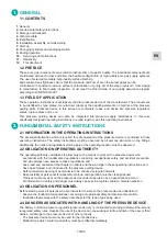
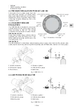
Line pressure regulators are used to reduce a higher tube pressure to a certain low supply pressure level.
They remain constantly installed inside the tube system. Pressure regulators LMD 500:
Fig. 4: Flow scheme FMD 500 - 21
1
Cylinder connection
2
Pressure regulator
3
Inlet pressure gauge
4
Outlet pressure gauge
5
Process gas valve
6
Relief valve
7
Purge gas valve
8
Non-return valve
5
4
8
1
6
2
3
7
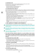
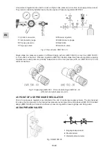
Single stage line pressure regulator in different design with six (LMD 500-03) or only four (LMD 500-01)
in- and outlet connections. Pressure regulators LMD 502: Double stage line pressure regulator supplying
constant level outlet pressure (virtually independent of the inlet pressure) with six (LMD 502-03) in- and
outlet connections.
Fig. 5: Single stage LMD 500 - 03 and double stage LMD 502 - 03
with inlet and outlet pressure valve
4.5 POINT OF USE PRESSURE REGULATOR
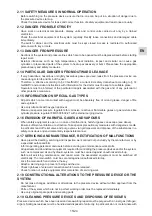
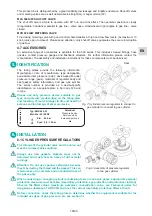
Point of use pressure regulators are installed at the end of central gas supply systems. The are designed
to reduce the line pressure to the desired low pressure level of gas consuming device. EMD 500: Standard
design (EMD 500-06) with inlet shut-off valve, pressure regulator, pressure gauge and fixing panel.
4.6 DIAPHRAGM VALVES
Fig. 6: EMD 500-06
1
Eingangsabsperrventil
2
Druckminderer
3
Hinderdruckmanometer
3
1
This product line is distinguished by a great reliability, low leakage and longlife endurance. Shut-off valves
and metering valves are as well deliverable in straight (G) or angel version (W).
MVA 500 G/W SHUT-OFF VALVE
The shut-off valve is simple to operate, with 90° turn and click effect. The open/shut position is clearly
recognizable: handwheel parallel to gas line – valve open. Handwheel at right angles to gas line – valve
closed.
MVR 500 G/W METERING VALVE
Fine dosing metering valve with good control characteristics at high and low flow levels. (at maximum 10
knob turns open to closed). Please keep attention: only shut-off valves guarantee the secure interruption
of gas flow.
4.7 ACCESSORIES
An extensive range of accessories is available for the 500 series. This includes screwed fittings, hose
nozzles, contact pressure gauges and flashback arresters. For further information please contact the
manufacturer. The assembly and installation instructions for these components must be observed.
IDENTIFICATION
5.
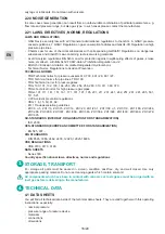
Fig. 7: Cylinder pressure regulator to connect to
gas cylinder to connect to gas cylinder
Seal
The rating plates provide the following information:
Manufacturer, date of manufacture, type designation,
permissible inlet pressure (pein), device-specific outlet
pressure range (paus), materials of regulator body and
seal gasket, safety information, and gas type symbol.
The serial number is provided as a device-specific
identification on a separate plate in bar code 128 and
in type.
Please use only pressure device suitable to gas
type and pressure predescriped on the rating plate
and labelling. Thread of danger to life and health of
persons and/or damage of pressure device.
Manufacturer
Attention!
Pressure device.
Service only by
autorised persons
He
Typ: EMD 400-01
Mat: Ms / Ni / PVDF
Pin: 40 bar
Pout: 0,5 - 10 bar
95.10.
INSTALLATION
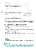
6.1 CYLINDER PRESSURE REGULATORS
The threads of the cylinder valve and the union nut
must be in impeccable condition.
Always use new gaskets. Gaskets must not be
deformed and must show no traces of dirt or metal
turnings.
Attention: Do not use spanner extensions because
they may destroy the thread and the gasket. This can
lead to leaks or to complete and uncontrolled loss of
the gas supply.
6.
Fig. 8: Assembly of pressure regulator
to the gas cylinder
When connecting or changing cylinders containing toxic or corrosive gases, appropriate personal
protection measures must be taken (respiratory protection, eye protection and protective clothing).
Observe the MAK values (maximum workplace concentration value; see Technical norms for
dangerous substances, TGRS 900) and have the correct respiratory protection filters at hand..
Before connection, check the rating plate to determine whether the equipment is suitable for the
intended use (type of gas, pressure, etc. see section 5).
Summary of Contents for druva LINE 200
Page 12: ......


