background image


JV-240UV User Manual 

36 


Chapter 5 Operating the JV-240UV 

5.1


Hardware Operation 

5.1.1


How to Set Flatbed Printing Mode 

NOTICE: 

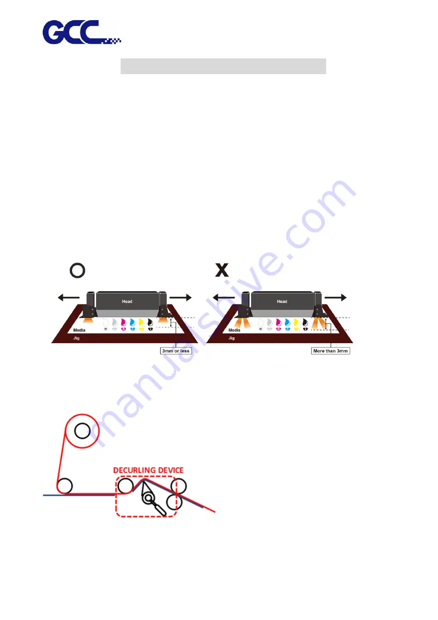
The factory setting of the height between print media and print head is 3mm. 

If the height between print media and print head is more than 3mm, it may cause ink droplet 

misting or splashing and lead to a grainy and uneven printing.   

When the height between print media and print head is more than 3mm, the reflected light from 

UV curing lamp increases and it can cause the misting ink to be cured, increase the ink visocosity 

and nozzel clogging, and hence damage print heads.   


NOTICE: 

  It is suggested to use the lamilator with decurling device to keep the sheet flat. 


Summary of Contents for JV-240UV

Page 1: ...JV 240UV User Manual http www GCCworld com GCC GCC Club V 2 2018 Sep ...

Page 2: ... is clearly on the cutting edge of all UV inkjet systems GCC understands that a creative technical background is the key to successful growth in the ever changing information economy We have a strong team of R D experts who propel our company to new heights From product development to manufacturing our engineers are dedicated to innovation and quality Guiding our solid technical base is a world cl...

Page 3: ... Manual 2 Release Note Version Change V 1 2017 Nov V 2 2018 Dec Add 6 8 How to replace alignment rule Add 5 1 1 Use the lamilator with decurling device to keep the sheet flat Add 5 1 6 How To Make Varnish Grayscale ...

Page 4: ...1 2 Set Ink Flow To Printer Heads 15 3 2Install JV 240UV VLCD 17 3 2 1 Install CCD driver 17 3 2 2 Install PlugInInstall driver 18 3 3 Set the IP Address of the spot varnish printer 20 3 3 1 How to IP Address 20 3 4 How to calibrate CCD Mark detection 21 Chapter 4 Control Panel 23 4 1Control Panel Workflow 23 4 1Control Panel Layout Description 30 Chapter 5 Operating the JV 240UV 36 5 1Hardware Op...

Page 5: ... Monthly Maintenance 72 6 2 1 Ink Print Head Cleaning 72 6 2 2 How To Turn On Off POWER SAVE Function 73 6 2 3 How To Dispose Waste Ink Bottle 74 6 2 4 Cleaning 75 6 3 Print Head Maintenance And Clean Up 76 6 3 1 Maintenance And Clean Up 76 6 3 2 Automatic Basic Cleaning Up Maintenance 79 6 3 4 Automatic Advanced Cleaning Up Maintenance 80 6 3 4 Manual Maintenance 82 6 4 How To Replace The Filter ...

Page 6: ...o Safety label Graphic Content 1 Warning The symbol indicates that fire is prohibited The ink and the fluid discharged out are highly flammable 2 High Voltage The symbol indicates high voltage Remove the lid could lead to expose to high voltage or electric shock 3 Warning The symbol indicates that the ink is health hazardous The ink and fluid discharged out is health hazardous avoid body contact 4...

Page 7: ...at during the printing process do not put your hands in the area to avoid your hands being pinched by moving parts 8 Keep Clear Warning The symbol indicates that do not put objects in addition to print media on the print area at all times to prevent print head being crashed by obstacles 9 Do Not Push Warning The symbol indicates that do not push carriage axis while moving the machine 1 2 Inks Safe...

Page 8: ...lations 1 3 First Aid Measures Contact by Remedy Inhalation Breathe in fresh air and consult a doctor in case of complaints Skin Immediately wash with soap and water then rinse thoroughly If skin irritation continues consult a doctor Eye First and for most flush your eyes with plenty of water Then tilt your head to prevent chemical from transferring to the uncontaminated eye Finally seek immediate...

Page 9: ...ent to be installed shall be stable and flat We suggest that you install the equipment in an air conditioned environment to control the appropriate temperature and humidity To ensure the equipment and the materials reach to the room temperature 24 hours prior in operation For the environment shall meet following conditions WARNING Prohibit on exposure under direct sun light Prohibit on setting up ...

Page 10: ...40UV User Manual 9 The operation environment for this equipment 22 to 30 C 71 6 F to 86 F 40 to 60 humidity Avoid locations with vibration Avoid locations with strong air current Avoid locations with flame ...

Page 11: ...color touch screen further increases operational convenience In the market applications of GCC JV 240UV spot varnish printer in addition to the advertisement catalog packaging printed matter etc the highlighted part needs to be implemented the local varnishing coating and the glazing pattern compared with the surrounding one should show more bright and beautiful appearance and strong stereoscopic ...

Page 12: ...ance 2 1 1 JV 240UV Front View H Touch screen control panel D Alignment ruler F Bulk Ink supply system E Front door G Emergency stop button K Print head set L CCD I Waste ink bottle C LED lamp A Maintenance J Printing area M Toolbox B Barometer ...

Page 13: ...JV 240UV User Manual 12 2 1 2 JV 240UV Rear view O Fuse R Ethernet Q USB P Power socket N Rear door T Side cover S Power switch ...

Page 14: ...isplay JV 240UV printing settings I Waste Ink Bottle Waste ink area When waste ink is full please take down the waste ink bottle and dispose it Please follow the local regulations to dispose the waste ink to prevent contaminating the environment J Printing Area The area where JV 240UV conducts the inkjet printing K Print Head Set Printing graphic image L CCD CCD M Toolbox Store commonly used tools...

Page 15: ...lease check the ink chip is inserted properly into the corresponding slot Step 2 Pour the Varnish into a large ink bottle labeled with a V label Step 3 Please plug in the power socket and turn on the power switch Note Please wait for 5 seconds to turn on turn off the power if you need to restart the machine ...

Page 16: ...k Flow To Printer Heads Step 1 Remove the thumbscrew and open the left cover Step 2 Open the ink valve Ink valve is opened Ink valve is closed Step 3 2 Select MENU 3 Select MAINTENANCE 4 Select INK INSTALL DRAIN 5 Select INK INSTALL FLOW ...

Page 17: ...e chips of each color Do not insert the chip of flush solution ENTER CANCEL Make sure the chips of each color are inserted properly and the chip of flush solution is removed ENTER CANCEL Seal the bottle caps ENTER CANCEL Check ink level YMCK low ink level Fill YMCK into ink bottles ENTER Ink pumping ENTER CANCEL The process is complete ENTER adequate ink inadequate ink Step 6 Close up the left cov...

Page 18: ...stall JV 240UV VLCD 3 2 1 Install CCD driver Step 1 Insert JV 240UV installation disk select JV 240UV CcdLibrary exe and perform installation Step 2 Select Next Step 3 Select installation path and then select Next Step 4 Select Next ...

Page 19: ...ete the JV 240UV Ccd installation 3 2 2 Install PlugInInstall driver Step 1 Select CCDMarkPlugin exe and perform installation Step 2 Select Install The computer must have installed Corel Draw Illustrator Step 3 Select OK Step 4 Select OK ...

Page 20: ...JV 240UV User Manual 19 Step 5 Select OK complete the CCDMarkPlugin installation ...

Page 21: ...240UV VLCD Step 2 Confirm the IP address of the machine and select the touch panel of the spot varnish printer Step 3 1 Select MENU on the control panel 2 Select NETWORK 3 Select IP Step 4 Enter IP select the value on IP Sub Mask Gateway confirm change the IP location required and select the return key Step 5 Start VLCD and Press Open option Step 6 In the IP Address field of VLCD input the same va...

Page 22: ...ate CCD Mark detection Step 1 Place the material printed with Mark dot on the origin of the XY coordinates of the spot varnish printer Step 2 Select Move To Mark JV 240UV spot varnish printer will start CCD automatically and move to Mark point ...

Page 23: ... Note CCD brightness control can be implemented through Light Level pull down menu after the completion of the adjustment press Set to confirm Step 4 Select Move To Home Step 5 Select Save Mark Note Learn Save Mark for the first time it is recommended to save the file and then read it directly from Load Mark Note The surface of the material on the market is different and it is recommended to relea...

Page 24: ...240UV User Manual 23 Chapter 4 Control Panel This section mainly describes JV 240UV Varnish Printer s touch screen control panel work flows and key operations 4 1 Control Panel Workflow Operating work flow ...

Page 25: ...JV 240UV User Manual 24 Operating work flow ...

Page 26: ...CLEANING MANUL CLEANING POWER SAVE VACUUM INK REMAINIING MAINTENANCE SYSTEM INFO OPTION NETWORK RESTORE DEFAULT SET1 SET2 SET3 PARAMETER AMC VACUUM LED POWER MANUL CLEANIING YES NORMAL POWERFUL X _______ Y _______ PURGE PH GAP AUTO DETECTION NOZZLE CHECK X Y ...

Page 27: ...JV 240UV User Manual 26 Operating work flow ...

Page 28: ...JV 240UV User Manual 27 Control panel flow O N FRONT REAR O N O N OFF OFF ...

Page 29: ...JV 240UV User Manual 28 Operating work flow Control panel flow IP 192 168 102 249 Sub Mask 255 255 255 0 Gateway 192 168 102 250 MAC Address 00 CF 52 72 03 01 RESTORE DEFAULT YES ON OFF ...

Page 30: ...40UV User Manual 29 PAUSE while printing Users can pause on the printing job by pressing the PAUSE button and proceed to cleaning procedure to improve printing quality Operating work flow Control panel flow ...

Page 31: ...n the vacuum will work when printing while when it is off the vacuum will not be carried out when printing ON OFF ON LOAD MADIA Set Place media height AMC Automatically detect the media height SmartPOSITION Set printing area MENU USER SET USER DEFAULT SET1 SET2 SET3 1 USER DEFAULT Initial parameters settings 2 SET1 3 parameter settings Adjust VACUUM BAND AAS OFFSET BI UNI setting Can store up to 3...

Page 32: ...MANUL CLEANING MANUL CLEANING When cleaning the print head manually the cartridge will move to maintenance area on the left hand side automatically for cleaning MENU POWER SAVE POWER SAVE Automatically switches off the display of control panel when the device hasn t been used for a set period of time allowable setting are 15 sec 30 sec 1 min 3 min and 5 min 3 MIN ...

Page 33: ...he printing operation ON OFF OFF MENU INK REMAINING INK REMAINING Check remaining ink volume 99 means there is sufficient ink 0 means short of ink need to refill ink immediately MENU MAINTENANCE REPLACE LED LAMP Automatically move the cartridge to the maintenance area on the left hand side for LED lamp replacement YES YES REPLACE WASTE INK BOTTLE Replace waste ink bottle YES YES INK INSTALL DRAIN ...

Page 34: ...tings FPGA Display FPGA version serial number based on factory version settings INK ID FPGA Display Ink ID FPGA version serial number based on factory version settings ENGINE FPGA Display ENGINE FPGA version serial number based on factory version settings MENU OPTION INCH User can choose between Metric or Imperial measurement Metric cm g Imperial unit inches oz Metric cm g LANGUAGE SET LCM display...

Page 35: ...ault YES MENU PH GAP AUTO DETECTION PH GAP AUTO DETECTION Automatically detect the gap between print head and media ON MENU TIME LOCKER TIME LOCKER Set the period of time that the machine can be operated The Time Locker function can be used for hire of a machine to schools or organizations to manage the rent duration of a hired machine OPTIONAL ...

Page 36: ... ON OFF ON PRINT CANCEL JOB CANCEL JOB Delete current print job ON PRINT PAUSED NORMAL CLEANING Normal print head cleaning ON POWERFUL CLEANING Powerful print head cleaning ON MANUL CLEANING When cleaning the print head manually the cartridge will move to maintenance area on the left hand side automatically for cleaning ON ...

Page 37: ...rint head is more than 3mm it may cause ink droplet misting or splashing and lead to a grainy and uneven printing When the height between print media and print head is more than 3mm the reflected light from UV curing lamp increases and it can cause the misting ink to be cured increase the ink visocosity and nozzel clogging and hence damage print heads NOTICE It is suggested to use the lamilator wi...

Page 38: ... set in FlexiPRINT The print quality may be decreased because the print head gap is not the optimum value 3 Continue to print by uni direction The throughput may be decreased and the quality may be slightly affected because the print mode is forced to set to uni direction and the print head gap is not the optimum value Under the following conditions the PH Gap Auto Adjustment Mode can be set to OF...

Page 39: ...JV 240UV User Manual 38 Workflow A Set the PH Gap Auto Adjustment to be ON on control panel The default setting ...

Page 40: ...JV 240UV User Manual 39 B Set the PH Gap Auto Adjustment to be OFF on the control panel ...

Page 41: ...instructions of rigid material printing Example 1 Set parameter settings of full table print size Please load the rigid material correctly according to following steps Step 1 Entre FLATBED mode Step 2 Select MENU Step 3 Select USER SET Step 4 Select DEFAULT and select BACK icon Step 5 Place print media on the lower right corner of the platen of JV 240UV CAUTION ...

Page 42: ...ted to apply AMC onto the highest position of the media Step 8 The computer sends the file complete Example 2 Set parameter settings of SmartPOSITION define a diagonal as print size Please load the rigid material correctly according to following steps Step 1 Entre FLATBED mode Step 2 Select MENU Step 3 Select USER SET Step 4 Select USER 1 and select BACK icon Note Choose USER1 USER2 USER3 to save ...

Page 43: ...etect the height between print media and print head Note It is suggested to apply AMC onto the highest position of the media Step 8 The computer sends the file complete Step 8 Select SmartPOSITION Step 9 Press the Arrow Keys to move the cartridge to the lower right corner of the print material and then press Position 1 icon then move cartridge again to the upper left corner of the print material a...

Page 44: ...the printing pattern and increase its scratch resistance Different varnish modes provide different visual effects not only offer high added value but also save coating equipment and labor costs Illustrator example Using Illustrator software to create varnish file please refer to the steps below Step 1 Create Varnish image It is suggested to create the Varnish image in monochrome Step 2 Select File...

Page 45: ...44 Step 3 Margin 10 50mm setting 10mm Size 3 10mm setting 5mm Step 4 Complete the 4 Mark points and open the finished Varnish layer Note Varnish layer is suggested to be filled with black Step 5 Select File Export Export As ...

Page 46: ...le set the settings in TIFF Options window then click OK Color Model Grayscale Resolution Other 720ppi Anti aliasing None Check LZW Compression Step 7 Open JV 240UV VLCD and click Add job Step 8 Select the tiff file that just created and click Open ...

Page 47: ...JV 240UV User Manual 46 Step 9 Right click on the file and click Job Properties Step 10 Select AAS Scan type 4 Markers Step 11 Select print mode parameters OK ...

Page 48: ...cs Base Printing Check Enable for bottoming before printing Level 1 Level 4 bottoming thickness of the ink Shape Pinning It can improve some material printing Varnish easily overflowing to effectively prevent the Varnish overflowing printing scope Step 12 Select the file and then select Send Step 13 Complete the setting of JV 240UV spot varnish printer and start printing CorelDraw Example Step 1 B...

Page 49: ...Select Tools Macro Run Macro select GlobalMacros JV 240UV_CCD_Mark gms and then select Run Step 3 Thickness 5 10mm setting 5mm Margin 10 50mm setting 10mm Explanation Make By Object Select the locating point at the edge of the object ...

Page 50: ...Mark points and open the finished Varnish layer Note Varnish layer is suggested to be filled with black Step 5 After the Varnish layer is opened select File Export select Save as type Tiff Step 6 Set Resolution in Convert to Bitmap window 720dpi Color mode Grayscale 8bit select OK and then complete ...

Page 51: ...To Create Custom Pattern for Varnish Printing Users are allowed to use graphic design software to create a preferred pattern and apply it for varnish printing to produce unique effect on the print media Follow the steps to create a custom pattern for varnish printing Microsoft Paint is used as an example here 1 Open Paint go to File under Properties ...

Page 52: ...JV 240UV User Manual 51 2 Select Pixels in Units column and set Width Length value The Width Length value must be a multiple of 8 i e 8 x 8 or 160 x 160 pixels 3 Create a desired pattern ...

Page 53: ... the location C Program Files x86 FlexiPRINT 10 5 1 GCC Edition Program GCCJF240UV TestPattern Varnish Mark 6 Save the jpeg file to the location C Program Files x86 FlexiPRINT 10 5 1 GCC Edition Program GCCJF240UV TestPattern Varnish Preview 7 The custom pattern for varnish printing is complete ...

Page 54: ...V User Manual 53 5 1 6 How To Make Varnish Grayscale Step 1 Open Photoshop Step 2 Create a new file and set the parameter Note Resolution 720dpi Color Mode Grayscale Step 3 Use Gradient Tool to fill the color ...

Page 55: ...JV 240UV User Manual 54 Step 4 Go to Image Mode Bitmap Step 5 Set the Output 720 Method select Diffusion Dither and then click ok Step 6 Complete gradient grayscale ...

Page 56: ...JV 240UV User Manual 55 Step 7 Go to file Save Step 8 Define the file name and select file type as TIFF and click Save Step 9 The process is complete ...

Page 57: ...ozzle v Check Bi directional v Check Color Offser v Check AMC v 5 1 8 Reset Back To The Factory Settings If messed up the parameter settings in the above operation user can select from the control panel follow the steps to reset back to the factory default Step 1 1 Select MENU on the control panel 2 Select RESTORE DEFAULT Enter RESTORE DEFAULT select YES option then press ENTER to complete the res...

Page 58: ...ct or not If there is defect in the print heads recommend cleaning up the print heads Step 1 Perform NOZZLE CHECK 1 Select MENU on control panel 2 Select NOZZLE CHECK 3 Set X and Y coordinates of NOZZLE CHECK pattern on the material and select CONFIRM Step 2 JV 240UV will execute Nozzle Check automatically to ensure the print head quality If there is blocked pixel in print head recommend to conduc...

Page 59: ... to conduct POWERFUL to clean up 1 Select MENU on the control panel 2 Select CLEANING 3 Select POWERFUL and the machine will proceed to POWERFUL cleaning Step 5 Conduct the printing test to ensure the print head blocked problem has been solved If the problem continues please conduct the 2nd cleaning cycle If the machine has been used for a long time recommend to clean manually 5 1 10 How To Pause ...

Page 60: ...equired while printing Step1 Select PAUSE button on the control panel Step 2 LCM shows Step 3 Select NORMAL CLEANING and press ENTER for NORMAL mode Step 4 Select POWERFUL CLEANING and press ENTER for POWERFUL mode Step 5 Complete cleaning select RESUME to continue Canceling job while printing Step1 Select PAUSE button on the control panel Step 2 Select CANCEL JOB on the control panel Step 3 Press...

Page 61: ...art the spot varnish printer and solve the problem 5 2 1 Read machine parameter values Follow the steps below to read the parameters from the machine when operating the machine for the first time Step 1 Start JV 240UV VLCD press Open option and select Parameters backup from machine and then JV 240UV VLCD will automatically read the parameters from the machine Note The detected parameter settings i...

Page 62: ... directional printing mode AAS Scan Type None No AAS detection before printing 4 Markers Read 4 AAS marks before printing Image Position X Y mm Image XY coordinates setting Default value is 0 0 Image scale X Y Adjust the image scale of media length and width Media type Save settings Save the parameters Delete media Delete the parameter Print origin offset X Y Set a new origin Paper Feeder enable P...

Page 63: ...on Learn Mark Learn AAS mark Move To Home Move the carriage back to the origin Print Settings Set the print menu Color to print Ink jet number UV lamp curing mode Normal Curing Regular curing mode Delay Curing Delay curing mode UV Power UV light energy Enable job repeat function Enable repeat function Enhance UV Curing Preform curing automatically after printing Save Store the parameters under Pri...

Page 64: ... Feeder Y Position Calibration Offset mm Calibrate the position of paper feeding Paper Height mm Calibrate the media length Feeder Paper Paper feeding test Take Paper Paper ejecting test Adjust Vacuum Position Feeder arm stretch Adjust the suction cup position Adjust Vacuum Back Feeder arm withdrawal Job ink use Job ink consumption V 0 0000CC Ink usage Read Read the previous ink usage PH PARAMETER...

Page 65: ...ibration is primarily used to ensure the uni directional bi directional printing precision Uni Directional Calibration 1 Start JV 240UV VLCD select Color Offset Color Offset and press Print 2 JV 240UV will automatically start Color Offset Test Pattern printing Following are horizontal alignment calibration examples 3 Use black to correct other colors 4 A total of 32 correction lines will be displa...

Page 66: ...er Step 3 Use a magnifying glass to observe that the V4 color and black lines are aligned to the 3 line Please record this number Step 4 After recording all the Numbers please go to the Color Offset V2 V3 V4 under the control interface of VLCD software to perform the horizontal fine tuning Example V2 120 3 117 VLCD input 117 V3 203 5 208 VLCD input 208 V4 282 3 279 VLCD input 279 Step 5 Enter all ...

Page 67: ...irectional Calibration 1 Start JV 240UV VLCD select Color Offset Bidirectional offset and press Print 2 JV 240UV will automatically start Color Offset Test Pattern printing 3 Select Color Offset Offset Bidirectional offset option ...

Page 68: ...of 32 correction lines will be displayed on the horizontal calibration pattern and the numbers are showed from left to right with the 16th line 0 showing the initial number 6 These figures will show the error values caused by the spots of various inkjet heads Example 1 The horizontal correction of V1 V2 V3 and V4 inkjet heads ...

Page 69: ...s are aligned to the 3 line Please record this number Step 4 Use a magnifying glass to observe that the V4 color and black lines are aligned to the 3 line Please record this number Step 5 After recording all the Numbers please go to the Bidirectional Offset V1 V2 V3 V4 under the control interface of VLCD software to perform the horizontal fine tuning Example V1 12 3 9 VLCD input 9 V2 10 5 15 VLCD ...

Page 70: ...JV 240UV User Manual 69 ...

Page 71: ...aintenance professionals To keep the flatbed printer in the best performance and the best printing quality it is necessary to periodically clean maintain this equipment with appropriate procedures 6 1 Check Remaining Ink and Refill Ink 6 1 1 Check Remaining Ink 1 Select MENU on the control panel 2 Select INK REMAININNG 3 Check remaining ink Description Green light indicates high ink level Yellow l...

Page 72: ...l the ink slowly to prevent the ink from overflowing 3 Must be replaced with ink bottle of the same type 4 Do not use the uncertified ink bottle 5 Do not pull out the ink bottle while the equipment is printing 6 Please do not remove the empty ink bottle until a new one is inserted Warning Do not store ink flush cleaning solutions or liquid drained out at any following locations Area might be expos...

Page 73: ...h Cleaner 26501007G to clean print head and print head area everyday Note Switch the ink valve off while cleaning and switch the ink valves on after the process is complete Print Head Cleaning 1 Select MENU on the control panel 2 Select MANUL CLEANING 3 Select ENTER press PURGE button and wait for 20 seconds then press 4 Remove thumbscrews and open the left cover and close ink valve Thumbscrew Cov...

Page 74: ...It is required to use sponge swabs with Cleaner 26501007G to clean print head and print head area every week and make sure that ink bottle is not empty and dispose waste ink bottle 6 2 2 How To Turn On Off POWER SAVE Function The function of POWER SAVE is to save energy When the device idles longer than a set period of time JV 240UV will automatically enter POWER SAVE mode Select POWER SAVE on the...

Page 75: ...ispose the waste ink according to the following steps 1 Select MENU on control panel 2 Select MAINTENANCE 3 Select REPLACE WASTE INK BOTTLE 4 Remove the waste ink bottle 5 Install the empty waste ink bottle NOTE Waste ink bottle contains hazardous substances Please DO NOT dispose the waste ink bottle with general garbage or discard it into sewage treatment system Please follow the local regulation...

Page 76: ...ting job before cleaning process starts Press the clip of ink valve to switch the ink valve off Ink valve is opened Ink valve is closed Note When the machine is in printing the moving parts might cause injury or high temperature components might cause burns While in cleaning up process please clean up ink residue or printing media on the platform and other area to avoid deposition Use cloth moiste...

Page 77: ...thly maintenance Apply automatic advanced cleaning up maintenance and wipe the print head with cleaning swabs Note When the machine idle 2 3day and the print head nozzle clog please click Powerful Clean to flush it each Powerful Clean process will take 8 min to complete the cycle Note When the machine is power down longer than 7 days please fill flushing solution into print head and drain the ink ...

Page 78: ...JV 240UV User Manual 77 Step3 Press the clip of ink valve to close it and turn off the machine Step4 Switch on the ink tube Step5 Take in cleaner 26501007G in syringe ...

Page 79: ...JV 240UV User Manual 78 Step6 Inject cleaner 26501007G into ink tube of print head Step 7 Switch off the ink tube Step 8 Close the tool carriage cover Step 9 Complete ...

Page 80: ...asic cleaning up instruction procedure to clean up print head prior the print job Step 1 Perform NOZZLE CHECK 1 Select MENU on the control panel 2 Select NOZZLE CHECK 3 Enter X Y value and press ENTER Step 2 JV 240UV will print out Nozzle Check test pattern if the printing quality is similar to the figure below please clean it up according to the following steps Step 3 ...

Page 81: ...he required printing quality If blocked area are filled then the basic clean up is completed 6 3 4 Automatic Advanced Cleaning Up Maintenance For the periodically cleaning up and maintenance if there is serious blockage in the print head it is recommended to apply advanced cleaning up instruction procedure to clean up print head prior the print job Step 1 Perform NOZZLE CHECK 1 Select MENU on the ...

Page 82: ...t out Nozzle Check test pattern if the printing quality is similar to the figure below please clean it up according to the following steps Step 3 1 Select MENU on the control panel 2 Select CLEANING 3 Select POWERFUL and JV 240UV will carry out automatic advanced cleaning up procedure ...

Page 83: ...clean up please remove any media on the JV 240UV printing platform 2 Don t use any tool other than the cleaning swab as it might damage the print head 3 Don t use the cleaning solution which used to soak the print head or cleaning solution which already has been used to clean up the print head It could lower the cleaning efficiency 4 For the manual cleaning please move very slowly and use the mini...

Page 84: ...open up the left cover Step 4 Press Purge switch for 3 seconds and wait for 20 seconds then press and close ink valve Step 5 Dip the cleaning swab into the cleaning solution bottle to moisten it Step 6 Check carefully if there are any residues of ink left on the area underneath the print heads Thumbscrew Cover Be sure to clean using One of the included Cleaning sticks ...

Page 85: ... Step 8 Open ink valve close up the left cover and fix it with thumbscrews and select 6 4 How To Replace The Filter Of LED Lamp Note It is suggested to change the filter of LED lamp every six months Step 1 1 Select MENU on the control panel 2 Select MAINTENANCE 3 Select REPLACE LED LAMP Thumbscrew Cover ...

Page 86: ...40UV User Manual 85 Step 2 Remove the thumbscrews and open the right cover Step 2 Turn off all ink valves Step 3 Turn off the power and unplug the power cord Step 4 Disconnect the Led Lamp wire Screw Cover ...

Page 87: ...ual 86 Step 5 Take apart the screw at the upper position which is connected with Led lamp set Step 6 Take apart the screws at the side position which is connected with Led lamp set Step 7 Take apart the screws 2 pieces ...

Page 88: ...sten the screws Step 9 Follow the procedures in reverse order from step 8 to step 5 to assemble the Led lamp Step 10 Plug in the power cord and restart JV 240UV The process is done 6 5 Ink Drain Away Step 1 Remove thumbscrews and open the left cover Thumbscrew s Cover ...

Page 89: ...ink valves Step 3 1 Select MENU 2 Select MAINTENANC 3 Select INK INSTALL DRAIN 4 Select INK DRAIN AWAY Step 4 Fill flush into flush channel by order of the instruction on control panel to complete the workflow of ink drain Step 5 Ink drain flow ...

Page 90: ...ead ENTER CANCEL Flush purging ENTER CANCEL Check Flush solution level Low flush solution level Fill flush solution into flush ink bottle 1 Use cotton swabs with Cleaner to clean print head and print head area 2 Empty the waste ink bottle ENTER CANCEL The process is complete ENTER adequate ink inadequate ink 1 Insert the chip of flush solution 2 Seal the bottle caps ENTER CANCEL Step 6 Assemble th...

Page 91: ...e machine on the left side to reset the pressure gauge with atmospheric pressure Step 1 Close all tube clip above print heads Step 2 Open the right side cover above main ink tank bottles Step 3 Remove the plugs at the bottom of air pressure buffer tank as soon as removed the plug the pump will keep pumping Figure 6 72 ...

Page 92: ...essure gauge with and buttons Note the default setting for pressure gauge is between 3 4 kpa according to local environment Adjust the pressure gauge to optimized value base on the weather condition to prevent ink from dripping Step 6 Put back the plug of air buffer tube Step 7 Install back the gauge cover and right side cover Step 8 Open the ink tube clip and complete the procedure ...

Page 93: ...ith any liquid or solid contaminants 2 The carriage must move back and forth on one side while injecting the grease 3 Users can apply manual lubrication or automatic lubrication to the Miniature linear rail for regular maintenance 4 There should always be lubricant coated on the surface of the rail 5 Apply the lubrication again before the oil changes color due to corrosion Lubrication Intervals 1 ...

Page 94: ... to replace alignment rule Step 1 Use cross screwdriver to remove the screws on the alignment rules on X and Y axis Replace the thin alignment rule by the thick one and fix it Step 2 The replacement of the alignment rules is complete ...

Page 95: ...is used on GCC verified materials GCC JV 240UV material parameter table NO Material Print Mode Print Color Directional LED Power 1 Chrome paper Production mode V Bi Directional 100 2 Matt finish paper Production mode V Bi Directional 100 3 Metallic finish paper Production mode V Bi Directional 100 ...

Page 96: ...n CCD module Print Speed 45 B3 sheet hr 1 Varnish Thickness 0 04 mm to 0 32 mm 2 Print accuracy 0 4mm Ink cartridges Type UV curable ink Capacity 1 Liter Colors Varnish Ink curing unit UV LED Lamp Control Panel Touch Screen 480 x 272 resolution Interface Ethernet Distance Accuracy When printing Error of less than 0 3 of distance traveled or 0 3mm 0 01 inch whichever is greater Voltage requirement ...

Page 97: ... heads with draft mode Higher varnish thickness will reduce print speed Media load time is not included 2 JV 240UV can achieve up to 320 microns in one print job with GCC recommended media Repeat the same print job can accumulate the varnish thickness to higher level Please visit GCC club for the latest user manual download GCC reserve the right to modify the user manual without notice ...

Reviews: