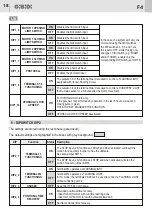
8 - DIP SWITCH DIP1
The settings are stored during the rest phase (gate closed
The default settings are highlighted in the boxes with grey background
.
).
DIP1_1
ON
PHOTOCELL
DURING
OPENING
OFF
Description
DIP
Status
Function
When the photocell is broken/interrupted during both opening and closing, the gate
motion is ceased until the photocell is re-made.
Subsequently the gate will always OPEN.
Breaking or interrupting the photocell during PAUSE will cause the pause-time
to begin counting down again.
The photocell stops and immediately inverts the gate motion during closing
while it is uninfluential during opening.
Breaking or interrupting the photocell during PAUSE will cause the pause-time
to begin counting down again.
DIP 3
1_
ELECTRIC LOCK
RELEASE STROKE
ON
Operation: following a START, OPENING or PEDESTRIAN command, the
following will occur in sequence:
• electric lock activation
• closing pulse of 1 second
• opening
• after 2 seconds, electric lock deactivation
Operation AT THE END OF CLOSING CYCLE (ONLY WITH SLOW-DOWN
ENABLED):
• extra movement in closing of 1 second with FORCE trimmer settings.
This function cannot be activated with a sliding gate configuration and is
unadvisable with electromechanical operators.
Electric lock release stroke disabled.
Simultaneous electric lock activation and opening.
OFF
ON
OPERATING
LOGIC
DIP 2
1_
AUTOMATIC logic
Operation in response to the START command:
STEP-BY-STEP WITH STOP logic
Operation in response to the START command:
• Gate closed
• Gate closed
• During opening
• During opening
• During closing
• During closing
• After a STOP
• Gate open
• Gate open (PAUSE)
OFF
(SEE PAUSE TRIMMER)
6.3A
T
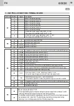
Protects the circuit board and the accessories.
160mA
T
F1
F2
6 - PROTECTION FUSES
Protects the circuit board and the motors.
7 - WARNING LEDs
Description
Type
Value
Position
RED
RED
RED
RED
RED
GREEN
GREEN
BLUE
FCCM2
FCAM2
FCCM1
FCAM1
PHOTO
START
PED
MEMO
L1
L2
L3
L4
L5
L6
L8
L9
Description
Signal
Colour
LED
Always on. Turns off when the CLOSING LIMIT SWITCH of motor 2 is reached.
Always on. Turns off when the OPENING LIMIT SWITCH of motor 2 is reached.
Always on. Turns off when the CLOSING LIMIT SWITCH of motor 1 is reached.
Always on. Turns off when the OPENING LIMIT SWITCH of motor 1 is reached.
Always on. Turns off when the photocell is broken/interrupted.
Comes on when the START command is activated and goes off when released.
Comes on when the PED. start command is activated and goes off when released.
RED
SAF. / STOP
L10
The control unit is blocked waiting to do the learning cycle.
It is necessary to do the learning cycle.
The control unit is in pre-learning phase after the activation of memo
button.
At rest and during the learning, the control unit is set for the operation
with 1 motor.
At rest and during the learning, the control unit is set for the operation
with 2 motors.
Learning correctly made.
Signalling made also on WARNING and FLASHING LIGHT.
Learning aborted. Check photo-stop-edge-ped inputs.
Signalling made also on WARNING and FLASHING LIGHT.
30s ON
0.3s ON - 0.3s OFF
0.3s ON - 0.3s OFF
0.3s ON - 1s OFF
X4
0.6s ON 0.6s OFF
CONTINUOUS
3s ON-1s OFF
X3
0.2s ON-2s OFF
CONTINUOUS
0.2s ON - 0.2s OFF
CONTINUOUS
0.2s ON - 1s OFF
Always on. It turns off after STOP/EDGE INPUT intervention.
16
UK
F4
17
UK
F4
If automatic closing is enabled then the gate stops
OPENS
STOPS
STOPS
Inverts the motion
If automatic closing is enabled (see PAUSE trimmer
function) then the pause-time begins again, otherwise it
closes. If automatic closing is enabled (as above) then a
permanent START command (always closed) will hold
the gate open, otherwise it closes.
OPENS
OPENS
UNINFLUENTIAL
Summary of Contents for F4
Page 13: ...NOTE NOTES 58 F4 IT UK...
Page 14: ...NOTE NOTES 59 F4...


