ENG
19
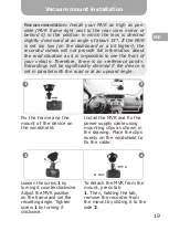
Fix the frame and the
mount of the device on
the windshield.
Loosen the screw
1
by
turning it counterclockwise.
Adjust the MVR position
on the frame and set the
recording angle. Tighten
screw
1
by turning it
clockwise.
Install the MVR and fix the
power supply cable using
mounting clips as shown in
the drawing. Place the clips
evenly on the windshield to
fix the cable.
To detach the MVR from the
mount, press tab
1
. Then, holding the tab,
remove the recorder from
the mount by sliding it to the
side
2
.
Vacuum mount installation
Recommendation:
Install your MVR as high as possible (MVR
frame right next to the rear view mirror or behind it) in the
position in which the lens is directed slightly downward at an
angle of about 15°. If the MVR is set too low (on the dashboard
or a bit higher), the recorded videos will not provide full
information about the road situation as it is impossible to see the
front of your vehicle. Therefore, there is no «reference point».
Recordings will be significantly dimmed if the device is set in
parallel with the road or at an upward angle.
Fix the frame and the mount of
the device on the windshield.
Install the MVR and fix the power
supply cable using mounting clips as
shown in the drawing. Place the clips
evenly on the windshield to fix the
cable.
Loosen the screw
1
by turning it
counterclockwise. Adjust the MVR
position on the frame and set the
recording angle. Tighten screw
1
by
turning it clockwise.
To detach the MVR from the mount,
press tab
1.
Then, holding the tab,
remove the recorder from the mount by
sliding it to the side
2.
1
3
4
1
1
2
Vacuum mount installation
2
Recommendation:
Install your MVR as high as pos-
sible (MVR frame right next to the rear view mirror or
behind it) in the position in which the lens is directed
slightly downward at an angle of about 15°. If the MVR
is set too low (on the dashboard or a bit higher), the
recorded videos will not provide full information about
the road situation as it is impossible to see the front of
your vehicle. Therefore, there is no «reference point».
Recordings will be significantly dimmed if the device is
set in parallel with the road or at an upward angle
.
Summary of Contents for F122G
Page 1: ...USER MANUAL MOBILE VIDEO RECORDER GAZER F122 F122g...
Page 2: ......
Page 3: ...User manual 4 18 19 33 34 48 ENG RU UA User manual 4 21 22 40 41 58 ENG RU UA...
Page 22: ...RU 22 1 23 2 24 3 25 4 26 5 27 6 29 7 31 8 33 9 36 10 37 11 3 38 12 40...
Page 23: ...RU 23 Gazer 20 60 5 55...
Page 24: ...RU 24 SD 30 10 0 5 20 10 RESET G 30...
Page 27: ...RU 27 USB miniUSB USB miniUSB REC OK 5 REC OK REC OK...
Page 28: ...RU 28 1 UP G MODE RETURN 30 Gazer F122 F122g Gazer F122 F122g GPS GPS GPS GPS...
Page 31: ...RU 31 1 2 3 REC OK MODE RETURN 4 UP DOWN REC OK MODE RE TURN 5 REC 6 7 MODE RE TURN REC OK...
Page 34: ...RU 34 PAL NTSC UP DOWN MODE 30 1 3 9M 4000x2250 16 9 6M 3264x1836 16 9 4M 2688x1512 16 9...
Page 35: ...RU 35 1 2 5 10 GPS GPS GPS G G 0 20 170 10 1 2 3 Speedcam...
Page 41: ...UA 41 1 42 2 43 3 44 4 45 5 46 6 49 7 50 8 52 9 55 10 56 11 3 57 12 58...
Page 42: ...UA 42 Gazer 20 60 5 55...
Page 43: ...UA 43 SD 30 10 0 5 20 10 RESET G 30...
Page 46: ...UA 46 USB miniUSB USB miniUSB REC OK 5 REC OK REC OK...
Page 47: ...UA 47 1 UP G MODE RETURN 30 Gazer F122 F122g Gazer F122 F122g GPS GPS GPS GPS...
Page 50: ...UA 50 1 2 3 REC OK MODE RE TURN 4 UP DOWN REC OK MODE RETURN 5 REC 6 7 MODE RE TURN REC OK...
Page 53: ...UA 53 9M 4000x2250 16 9 6M 3264x1836 16 9 4M 2688x1512 16 9 PAL NTSC UP DOWN MODE 30 1 3...
Page 54: ...UA 54 1 2 5 10 GPS GPS GPS G G 0 20 170 10 1 2 3...
Page 59: ......
Page 60: ......


