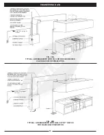
FIG. 24
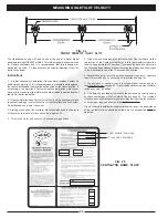
FRONT VIEW OF INLET SLOT
FIG. 26
VENTILATOR NAME PLATE
24
MEASURING INLET SLOT VELOCITY
TOTAL SUPPLY CFM HERE
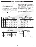
The illustrations on page 23 and 24 show the use of a Pacer digital
anemometer model DA4000 or DA40. This is the standard instrument used
for Gaylord ventilators and it is recommended that this instrument or
equivalent be used. To take accurate air velocity readings, follow the
instructions below.
Instructions
1. It is first necessary to determine if the ventilator includes Custom Air
baffles as shown in fig. 23B. If shop drawings are available, and if equipped,
the custom baffles and their location will be noted on the front elevation. If
not available, to determine if Custom Air baffles are provided, place your
hand over the lower lip of the inlet slot and slide it along the entire length of
the slot to feel for the baffle.
2. If the ventilator includes Custom Air baffles, it will be necessary to take
two sets of readings - one for the section of ventilator that includes Custom
Air baffles and one where it does not.
3. Starting at one end of the ventilator, place the probe head in the middle
of the slot on the inlet slot plane as shown in figure 23A.
4. Turn on the meter and push the 16 second average button.
5. Slide the probe head along the slot to the end of the ventilator or to the
intersection of the Custom Air baffle, at a rate that would complete the
reading in approximately 16 seconds. If you reach the end of the slot before
the 16 seconds has elapsed, without removing the probe head slide it back
in the other direction until the 16 seconds has expired.
6. Record the velocity (fpm) on the start up inspection report form. A sample
report form, which can be photocopied, is provided on page 44.
7. The designed, or optimum velocity is noted on the shop drawings and
the Air Velocity Chart on page 23. Two velocities will be noted if the ventilator
includes custom air baffles.
8. Compare the recorded air velocity to the designed air velocity shown
on the shop drawings or the Air Velocity Chart on page 22. The recorded
velocity may be slightly lower or higher providing that it is within the minimum
and maximum range as shown on the Air Velocity Chart .
If the air velocity is outside the minimum/maximum range, the performance
of the ventilator will be affected and therefore the exhaust fan must be
adjusted.
TOTAL EXHAUST CFM HERE
Summary of Contents for CG Series
Page 34: ...32 DETERGENT PUMP ...
Page 35: ...33 MISCELLANEOUS VENTILATOR PARTS ...
Page 36: ...34 WIRING DIAGRAM FOR GPC 5000 WITH ELECTRIC FIRE DAMPER 120 VOLT ...
Page 37: ...35 WIRING DIAGRAM FOR GPC 5000 WITH FUSE LINK FIRE DAMPER 120 VOLT ...
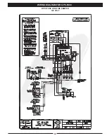
Page 38: ...WIRING DIAGRAM FOR GPC 5000 S5 WITH ELECTRIC FIRE DAMPER 120 VOLT 36 ...
Page 39: ...WITH FUSE LINK FIRE DAMPER 120 VOLT WIRING DIAGRAM FOR GPC 5000 S5 37 ...
Page 40: ...WIRING DIAGRAM FOR GPC 5000 WITH ELECTRIC FIRE DAMPER 220 VOLT 38 ...
Page 41: ...WITH FUSE LINK FIRE DAMPER 220 VOLT WIRING DIAGRAM FOR GPC 5000 39 ...
Page 42: ...WIRING DIAGRAM FOR GPC 5000 S5 WITH ELECTRIC FIRE DAMPER 220 VOLT 40 ...
Page 43: ...WITH FUSE LINK FIRE DAMPER 220 VOLT WIRING DIAGRAM FOR GPC 5000 S5 41 ...
Page 46: ......


