Each Gaylord Ventilator is engineered to properly ventilate the
specific cooking operation. The exhaust air volume is engi-
neered as a specific volume per lineal ft. of ventilator and is
determined by the type of cooking equipment being ventilated.
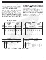
The following Air Volume Chart lists the various volumes per
lineal ft. designs.
A ventilator may be designed to operate at two different air
volumes. For example, half the ventilator may operate at 150
CFM/Lin. Ft. by utilizing “Custom Air” Baffles, and the other
half at 250 CFM/Lin. Ft.
Refer to “Measuring Inlet Slot Velocity” on Page 22 for
instructions on how to determine the designed Air Volume/Lin.
Ft.
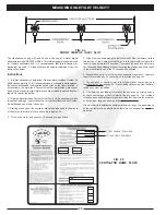
The total exhaust volume for each ventilator is stamped on the
ventilator nameplate. (Refer to Figure 26 on Page 24.)
DUCT VELOCITY
Based on 1800 FPM (9.14 M/S)
WATER TEMPERATURE REQUIREMENTS
WATER PRESSURE REQUIREMENTS
WATER CONSUMPTION
The length of the wash cycle may be set for 3 different times,
3 minutes for light-duty equipment, 5 minutes for medium-duty
equipment, and 9 minutes for heavy-duty equipment.
ELECTRICAL REQUIREMENTS
Standard voltage 120 volt, 60 Hz. Provide 24 hour, 20 amp
service.
Optional voltage 220 volt, 50 Hz. 220 volt. All controls are
marked with their operating voltage. See pages 34 through 41.
MAKE-UP AIR
Make-up air must be supplied for replacement of air exhausted
through all kitchen exhaust systems. Make-up air should be
delivered through registers at ceiling height and distributed
throughout the kitchen. A general "rule of thumb" is that 75%
to 80% of the replacement air should be fresh, conditioned
(heated or cooled) air brought into the kitchen area -- with the
remaining 20% to 25% allowed to flow into the kitchen from
adjacent areas.
NOTE: RECOMMENDED PERCENT OF MAKE-UP AIR FOR
"MA" SERIES VENTILATORS INCORPORATING INTEGRAL
MAKE-UP AIR WILL VARY. REFER TO THE GAYLORD
MASTER ENGINEERING DATA SHEET FOR SPECIFIC
REQUIREMENTS.
NOTE: AIR VOLUME AND STATIC PRESSURE REQUIRE-
MENTS ARE BASED UPON OPERATION AT MEAN SEA
LEVEL UNLESS OTHERWISE INDICATED. AIR VOLUME
AND STATIC PRESSURE MUST BE CORRECTED FOR
HIGH ALTITUDES.
17
ENGINEERING DATA
Model AB, BD, BDL Series,
and C & E up to 300
CFM/FT. only.
Model
BDL-DS
Series
Model AB, BD, BDL Series,
and C & E up to 300
CFM/FT. only.
Model
BDL-DS
Series
(Imperial)
250 Extractor
400 Extractor
& DS Series
CG Series
1.0
GPM/FT
1.60
GPM/FT
RG Series
.50
GPM/FT
.80
GPM/FT
(Metric)
250 Extractor
400 Extractor
& DS Series
CG Series
.208
L/S/METER
.331
L/S/METER
RG Series
.104
L/S/METER
.166
L/S/METER
IMPERIAL
METRIC
40 PSI Min. - 80 PSI Max.
2.8 kg/cm - 5.6 kg/cm
IMPERIAL
METRIC
140°F Min. - 180°F Max.
60°C Min. - 82°C Max.
T
R
A
H
C
E
M
U
L
O
V
R
I
A
)
l
a
i
r
e
p
m
I
(
d
e
r
i
s
e
D
r
e
P
M
F
C
t
o
o
F
l
a
e
n
i
L
c
i
t
a
t
S
e
r
u
s
s
e
r
P
t
c
u
D
t
A
r
a
ll
o
C
*
0
5
1
0
5
2
0
0
3
0
5
3
0
0
4
0
5
4
0
0
5
3
3
.
1
3
3
.
1
0
7
.
1
5
6
.
1
5
6
.
1
0
0
.
2
0
4
.
2
l
a
t
o
T
s
t
o
l
S
h
t
o
B
0
0
4
0
0
5
0
5
.
1
5
1
.
2
s
e
l
f
f
a
B
r
i
A
m
o
t
s
u
C
h
t
i
W
*
T
R
A
H
C
E
M
U
L
O
V
R
I
A
)
c
i
r
t
e
M
(
d
e
r
i
s
e
D
.
c
e
S
/
S
R
T
L
l
a
e
n
i
L
r
e
P
r
e
t
e
M
c
i
t
a
t
S
e
r
u
s
s
e
r
P
s
l
a
c
s
a
P
t
A
)
A
P
(
r
a
ll
o
C
t
c
u
D
*
7
2
2
9
7
3
4
5
4
0
3
5
6
0
6
1
8
6
7
5
7
1
3
3
1
3
3
3
2
4
1
1
4
1
1
4
8
9
4
7
9
5
l
a
t
o
T
s
t
o
l
S
h
t
o
B
6
0
6
7
5
7
3
7
3
5
3
5
s
e
l
f
f
a
B
r
i
A
m
o
t
s
u
C
h
t
i
W
*
Summary of Contents for CG Series
Page 34: ...32 DETERGENT PUMP ...
Page 35: ...33 MISCELLANEOUS VENTILATOR PARTS ...
Page 36: ...34 WIRING DIAGRAM FOR GPC 5000 WITH ELECTRIC FIRE DAMPER 120 VOLT ...
Page 37: ...35 WIRING DIAGRAM FOR GPC 5000 WITH FUSE LINK FIRE DAMPER 120 VOLT ...
Page 38: ...WIRING DIAGRAM FOR GPC 5000 S5 WITH ELECTRIC FIRE DAMPER 120 VOLT 36 ...
Page 39: ...WITH FUSE LINK FIRE DAMPER 120 VOLT WIRING DIAGRAM FOR GPC 5000 S5 37 ...
Page 40: ...WIRING DIAGRAM FOR GPC 5000 WITH ELECTRIC FIRE DAMPER 220 VOLT 38 ...
Page 41: ...WITH FUSE LINK FIRE DAMPER 220 VOLT WIRING DIAGRAM FOR GPC 5000 39 ...
Page 42: ...WIRING DIAGRAM FOR GPC 5000 S5 WITH ELECTRIC FIRE DAMPER 220 VOLT 40 ...
Page 43: ...WITH FUSE LINK FIRE DAMPER 220 VOLT WIRING DIAGRAM FOR GPC 5000 S5 41 ...
Page 46: ......


