background image

Your First Solo Flight

By now you’ve unpacked your Gateway 2000 Solo™ Multimedia Notebook, and you’re just a few
steps from really taking off.

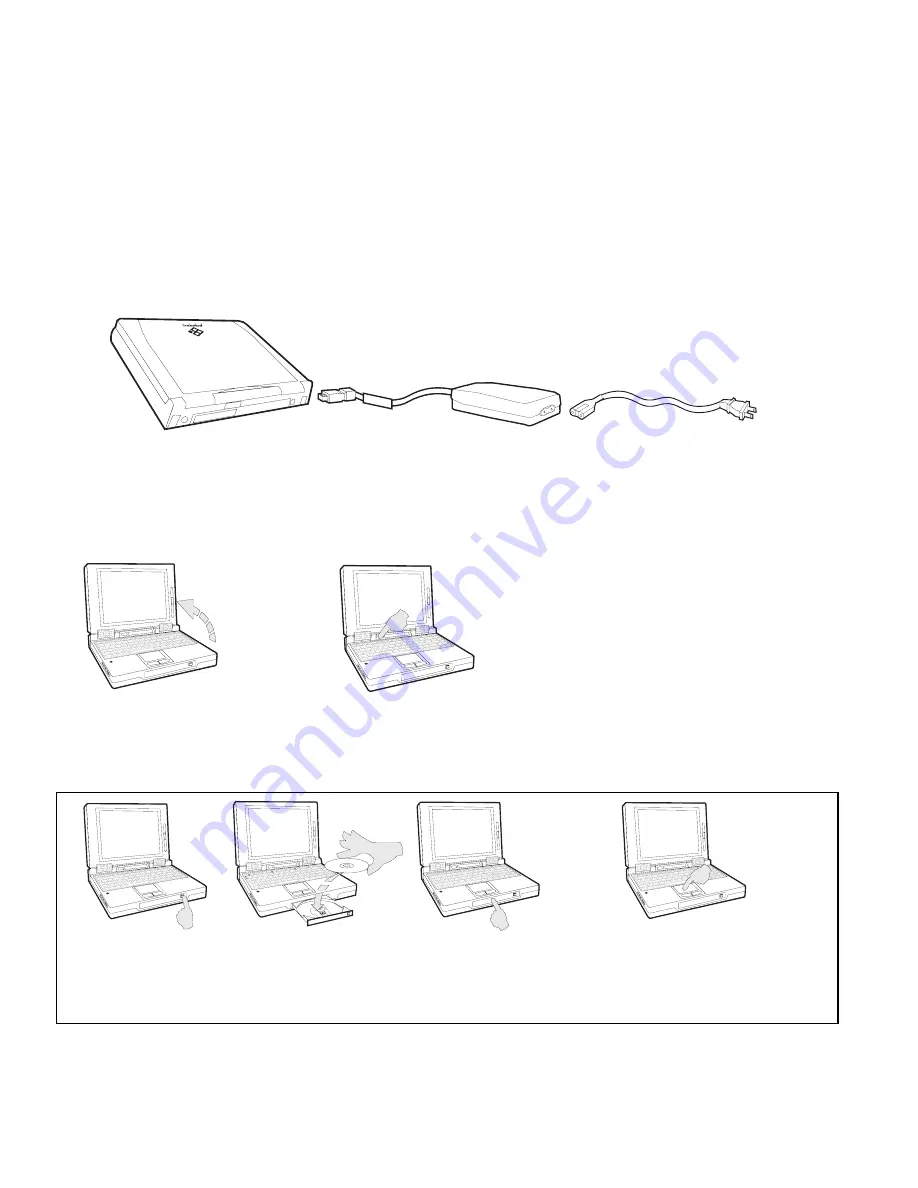
1. If you haven’t done so already, take the time now to connect your unit to an AC power

source as shown below.

(Use AC power as the battery in your unit is probably dead. An installed battery automati-
cally charges itself, however, as long as the unit is connected to AC power. In order to
optimize the battery’s life and performance, allow it to charge overnight and then completely
discharge it through normal use. Do this twice for best results.)

The AC adapter

The AC power cord

4. The Windows

®

 95 logo

appears on the screen.
(Windows

®

 for Workgroups

users must type 

win

 at the

C: prompt and press Enter.)

2. Slide the

cover latch to
the right to
open the unit.

3. Press the

power
button to
turn the unit
on.

A. Press the eject

button on the
CD-ROM drive.

B. Insert the Gateway

2000 Solo System
CD
.

C. Close the drive

tray.

D. Slide a finger on the pad to move

the cursor onto the MEETSOLO
icon in the CD’s directory. Tap
twice to double-click the icon.

The unit

5. Your system is now ready to fly. Continue navigating your own path, or, if the CD-ROM

drive is installed, follow the steps below to take a quick ride with the Gateway 2000 Solo
System CD
.

Summary of Contents for MULTIMEDIA NOTEBOOK SYSMAN017AAUS

Page 1: ...USER S GUIDE ...

Page 2: ...through normal use Do this twice for best results The AC adapter The AC power cord 4 The Windows 95 logo appears on the screen Windows for Workgroups users must type win at the C prompt and press Enter 2 Slide the cover latch to the right to open the unit 3 Press the power button to turn the unit on A Press the eject button on the CD ROM drive B Insert the Gateway 2000 Solo System CD C Close the d...

Page 3: ... 13 Battery power 13 Bridge battery 15 Starting Stopping and Restarting 15 Standby mode 16 Suspend mode 16 Rebooting 16 Modular Option Bay 17 CD ROM Drive 18 Floppy Disk Drive 18 External Floppy Drive 19 Hard Disk Drive 19 PCMCIA Cards 21 Memory 22 Connections 23 IR module 23 Docking bar 23 Setup Menus 25 Main Setup Menu 25 Password Setup Menu 26 Port Assignment Menu 27 Power Management Menu 28 Mi...

Page 4: ...The Gateway 2000 SOLO Multimedia Notebook User s Guide ...

Page 5: ...type anbefalt av apparatfabrikanten Brukte batterier kasseres i henhold til fabrikantens instruksjoner Legal notices Gateway 2000 Solo Multimedia Notebook User s Guide Copyright 1995 Gateway 2000 610 Gateway Drive North Sioux City SD 57049 USA All rights reserved This book is protected by copyright and all rights are reserved No part of it may be reproduced or transmitted by any means or in any fo...

Page 6: ... voltages that can cause serious personal injury or death Return defective AC adapters to Gateway 2000 The AC adapter is intended for use with a computer Both must meet EN 60950 ACHTUNG Netzkabel stets in eine gut zugängliche Steckdose nahe der Ausrüstung einstecken um durch einfaches Ziehen des Steckers jederzeit die Stromversorgung unterbrechen zu können Den Adapter unter keinen Umständen ausein...

Page 7: ...56 colors Mouse Pointer EZ Pad integrated pointer PS 2 type connector for external mouse CPU Intel P54CLM 75 or P54CLM 90 low power Pentium Processor Cache 16K in CPU 256K pipelined burst synchronous external CPU speed 75 or 90MHz BIOS 256K includes configuration utility with password security and power management RAM type 70ns 3 3V low power DRAM RAM capacity 8MB on board expandable to 16 24 or 4...

Page 8: ...y pack 14 4DC 2700mAh lithium battery batteries can be hot swapped without rebooting Recharges in or out of system Conforms to APM 1 1 Permanent internal NiMH battery maintains system memory for about one half day with battery pack removed Battery life 38 88 watt hours 2 5 to over 4 hours in typical usage under Windows fully charged battery lasts about three weeks in Suspend mode Charging cycle Va...

Page 9: ...ect the docking bar here See page 23 VGA port VGA port VGA port VGA port VGA port connect any standard monitor here See page 12 AC AC AC AC AC connector connector connector connector connector connect AC adapter here See page 13 PS 2 PS 2 PS 2 PS 2 PS 2 port port port port port connect a mouse or keyboard here See pages 9 and 11 Cover latch Cover latch Cover latch Cover latch Cover latch slide to ...

Page 10: ...utton reset button reset button reset button reset button flip it down to reveal flush PCMCIA slots and reset button See pages 21 and 16 Volume control Volume control Volume control Volume control Volume control turn to adjust volume of built in speakers or headphone jack This control does not affect the volume of the Line Out jack on the docking bar Line input jack Line input jack Line input jack...

Page 11: ...ve is accessed IR port IR port IR port IR port IR port lit when IR port is enabled Monitor switch Monitor switch Monitor switch Monitor switch Monitor switch lit when external monitor port is active Standby Standby Standby Standby Standby lit when unit is in standby mode See page 16 Floppy disk Floppy disk Floppy disk Floppy disk Floppy disk lit when internal floppy drive is accessed Serial port S...

Page 12: ...key key key key Scroll Lock Scroll Lock Scroll Lock Scroll Lock Scroll Lock key key key key key Fn function Fn function Fn function Fn function Fn function key key key key key Function Function Function Function Function keypad keypad keypad keypad keypad Keyboard The system features a specially designed 86 key keyboard In order to provide the full functionality of a 101 key keyboard many of these...

Page 13: ...ol mode of function keypad Function keypad See below functions as either numeric or cursor control keypad Function keypad The keys of the function keypad produce the following standard lowercase letters numerals and punctuation when pressed alone standard uppercase letters and symbols when pressed with the Shift key numerals and symbols when pressed with the Fn and Num Lock keys cursor movements w...

Page 14: ... to the unit through the PS 2 port on the back of the unit See page 6 or the PS 2 mouse port on the docking bar See page 24 Built in microphone stereo speakers Because of their proximity to each other the built in microphone may cause feed back in the internal stereo speakers if both are used at the same time For this reason your unit was shipped with the built in microphone turned off It may be t...

Page 15: ...extended period of time that image may remain on the screen for a while as a slight shadow Although this shadow is temporary and will disappear eventually a screen saver program should be used to maintain optimum image quality An external monitor may be attached to the unit through the VGA port located on the back of the unit See page 6 or on the docking bar See page 24 If you attach an additional...

Page 16: ...d We recommend that you completely charge and discharge the battery twice as soon as possible as this improves the accuracy of the unit s battery power gauge and optimizes the battery s life and performance Charging discharging the battery The battery must be connected to an AC power source for about 2 and one half hours to charge completely The unit can run on a fully charged battery for about 3 ...

Page 17: ...he unit Simply remove the battery from the unit s case as shown below and connect it directly to the AC adapter AC connector AC connector AC connector AC connector AC connector Step 1 Step 1 Step 1 Step 1 Step 1 Disconnect the AC adapter turn the unit over and slide the battery latch away from the battery Step 2 Step 2 Step 2 Step 2 Step 2 While holding the latch place a fingertip in the indention...

Page 18: ...shut down the system be sure to save all work before pressing the power button Power button Power button Power button Power button Power button press once to turn the unit on Step 2 Step 2 Step 2 Step 2 Step 2 Locate the bridge battery under the HDD bay Step 1 Step 1 Step 1 Step 1 Step 1 Remove the hard disk drive as shown on page 20 Hard disk drive Hard disk drive Hard disk drive Hard disk drive ...

Page 19: ...t off but it is actually using a very small amount of power to save your work for up to three weeks Of course work should still be saved to the hard drive as often as possible because the Suspend save only lasts as long as the unit is in Suspend mode To exit Suspend mode open the cover and press the power button Rebooting If the system stops responding to the EZ Pad or the keyboard it has experien...

Page 20: ...tch between drives remove the installed drive or bay cover from the unit s modular bay as shown below and replace it with a different drive The system is upside down at this point so the drive being installed must be turned upside down as well Bay access Bay access Bay access Bay access Bay access panel panel panel panel panel Release latch Release latch Release latch Release latch Release latch S...

Page 21: ...nstalled it must be rebooted When the floppy disk drive is installed and active the floppy disk drive icon lights in the status display bar See page 8 Open button Open button Open button Open button Open button press to open CD tray after installation CD ROM drive CD ROM drive CD ROM drive CD ROM drive CD ROM drive top view from the front CD ROM drive CD ROM drive CD ROM drive CD ROM drive CD ROM ...

Page 22: ...ar icons Hard Disk Drive The system s hard disk drive HDD may be removed from the unit for replacement or for switching between different hard drives The instructions on the following page detail the procedure for removing and replacing the hard disk drive Step 1 Step 1 Step 1 Step 1 Step 1 connect the cable s parallel connector to the unit s or the docking bar s floppy parallel port Step 2 Step 2...

Page 23: ...se HDD release HDD release HDD release HDD release latch latch latch latch latch Step 4 Step 4 Step 4 Step 4 Step 4 Grasp the latch and lift the hard drive up and out of the HDD bay The HDD may need to be slid backwards to free it from the unit Step 3 Step 3 Step 3 Step 3 Step 3 With the release latch up slide the hard drive toward the front of the unit Step 1 Step 1 Step 1 Step 1 Step 1 Gently lo...

Page 24: ...PCMCIA slot Because the system supports hot swapping one card can usually be exchanged for another by simple removal and replacement Step 1 Step 1 Step 1 Step 1 Step 1 Flip open the PCMCIA door on the left side of the unit Step 2 Step 2 Step 2 Step 2 Step 2 Select a PCMCIA card to install PCMCIA slot PCMCIA slot PCMCIA slot PCMCIA slot PCMCIA slot 2 shown Eject buttons Eject buttons Eject buttons ...

Page 25: ...modules are installed in the memory sockets as shown below Step 1 Step 1 Step 1 Step 1 Step 1 Enter the Main Setup Menu set the power switch to ON OFF and exit saving changes See page 25 and 26 Step 2 Step 2 Step 2 Step 2 Step 2 Press the Power button to turn the unit off close the lid disconnect the AC power and remove the battery Step 3 Step 3 Step 3 Step 3 Step 3 Turn the unit over and lift awa...

Page 26: ...bar or port replicator duplicates many of the connectors and ports found on the back of the unit as well as a line out jack for audio a game port and an extra PS 2 port Peripheral devices such as an external keyboard mouse or joystick connect to the bar which then connects to the system Serial port connector Serial port connector Serial port connector Serial port connector Serial port connector co...

Page 27: ... 1 Step 1 Step 1 Close the port cover and slide the small panel in front of the docking bar port to the right Step 2 Step 2 Step 2 Step 2 Step 2 Align the docking bar s connec tor with the unit s port Press the docking bar to the unit Step 3 Step 3 Step 3 Step 3 Step 3 Rotate the docking bar s locks to secure it to the Solo Step 4 Step 4 Step 4 Step 4 Step 4 Connect peripherals to the docking bar ...

Page 28: ...rd port assignments power management keyboard setup and other functions See pages 26 29 Exit the Setup Menus by pressing the Esc key The highlighted box on any of the Setup Menus indicates which option is selected The arrow keys control the position of this box To select an option from the left side of the Main Setup Menu press the appropriate arrow key s to move the highlighted box onto the desir...

Page 29: ...press Spacebar to toggle between ON OFF system reboots or shuts off completely when switch is pressed SUSPEND RESUME system enters suspend mode or resumes from suspend mode when switch is pressed After changing an option feel free to change another option select another menu or exit the Setup Menus To select one of the Additional Setup Menus from the right side of the Main Setup Menu press the app...

Page 30: ...ns After setting options the screen automatically returns to the Main Setup Menu Option To Change Serial Port select press Spacebar to toggle between COM1 COM2 COM3 COM4 or DISABLED IR Port select press Spacebar to toggle between COM1 COM2 COM3 COM4 or DISABLED Parallel Port select press Spacebar to toggle between LPT1 LPT2 LPT3 or DISABLED Parallel IRQ select press Spacebar to toggle between IRQ5...

Page 31: ...Change Maximum Battery Life see screen select press Enter Good Battery Life see screen select press Enter Good Performance see screen select press Enter Maximum Performance see screen select press Enter User Settings Battery sets Battery options select press Enter new menu screen appears see screen below select and set options individually with arrow keys press Enter press Esc User Settings AC set...

Page 32: ...or DISABLED Keyboard Setup Menu This menu allows you to control the unit s keyboard Access this menu from the Main Setup Menu See page 25 The following chart details the process for setting the Keyboard Setup options After setting option press En ter to return to the Main Setup Menu Option Function To Change Key Switch switches Ctrl and Caps keys select Caps and Ctrl keys highlighted press Spaceba...

Page 33: ...led properly See page 19 Has it recently been subjected to an excessive amount of static electricity or physical shock Reinstall system files from the Gateway 2000 Solo System CD Is the unit attempting to boot from the floppy drive first See page 26 Battery if using battery power Is it installed See page 13 Is the battery icon on the status display bar lit or blinking See pages 8 and 14 Is it char...

Page 34: ...stomer Support The screen says Non system disk or disk error reading drive A You have a non bootable disk in drive A the floppy disk drive Remove it and press any key The screen says Bad command or file name You may have mistyped a command Retype the command or check your operating systems manual For information on other error messages refer to the manuals that document your operating system The u...

Page 35: ...8 23 K Keyboard 4 6 8 9 16 23 24 25 29 KeyboardSetupMenu 29 L Lineinput 7 Line out 7 23 24 M Main Setup Menu 12 22 25 26 27 28 29 Memory 4 7 22 Menu 9 10 12 13 22 25 26 27 28 29 Microphone 7 8 11 MiscellaneousMenu 29 Modular option bay 6 17 Mouse 4 6 8 11 23 24 See also EZ Pad N Num Lock 8 9 10 31 P Pad Lock 8 9 10 31 Password 4 25 26 27 31 Password Setup Menu 26 PCMCIA 4 5 7 16 21 Pointer 4 Port ...

Page 36: ...for your particular needs In most cases we will need your Customer ID number and order number so please have these available when you call Customer Service 800 846 2000 Fax 605 232 2445 Technical Support 800 846 2302 U S 800 846 3609 Canada Puerto Rico Fax 605 232 2445 Add on Components 800 846 2080 Fax 605 357 1023 International Callers 605 232 2191 FaxBack Service 800 846 4526 Gateway 2000 BBS 6...

Page 37: ...SYSMAN017AAUS 8 95 ...

Reviews: