background image

Chapter 2: Hardware Basics

www.gateway.com

8

Back


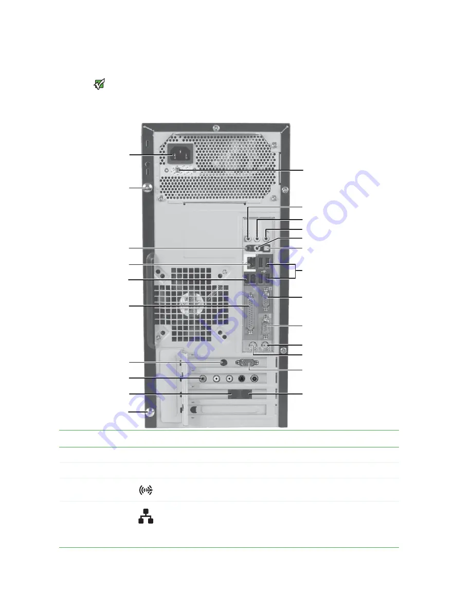
Important

Your computer hardware options and

port locations may vary from the

illustration below.

Modem jack

Serial port

PS/2 keyboard port
PS/2 mouse port

Voltage switch

Power connector

Ethernet (network) jack

Monitor port

Audio in/side speaker jack

Case cover thumbscrew

Headphone/front speaker jack
Microphone jack
Center/subwoofer jack (optional)

Rear speaker jack

(optional)

USB ports

Monitor port 
(optional)

Telephone jack

S-Video out jack

(optional)

S/PDIF jack (optional)

IEEE 1394/FireWire™/

i.Link™ ports (optional)

Parallel port

TV Tuner (optional)

Case cover thumbscrew

Component

Icon

Description

Power connector

Plug the power cord into this connector.

Case cover thumbscrews

Remove these screws before opening the case.

Rear speaker jack
(black plug) (optional)

Plug your rear right and left speakers into this optional jack.
For information on configuring this jack, see the User Guide.

Ethernet (network) jack

Plug an Ethernet network cable or a device (such as a DSL or cable modem for a broadband 
Internet connection) into this jack.
For more information, see “Learning about the Internet” in your 

User Guide 

which has been 

included on your hard drive. To access this guide, click 

Start

All Programs

, then click 

Gateway 

Documentation

.

Summary of Contents for GT4015

Page 1: ...HARDWARE REFERENCE R F RENCE MAT RIELLE Gateway Computer Ordinateur Gateway...

Page 2: ...12 Removing the front bezel 13 Closing the case 14 Replacing the front bezel 14 Replacing the side panel 14 Installing memory 15 Replacing the system battery 16 Adding or replacing a CD or DVD drive 1...

Page 3: ...Contents www gateway com ii...

Page 4: ...CHAPTER 1 1 AboutThisReference About this guide Accessing the User Guide Gateway contact information Microsoft Certificate of Authenticity...

Page 5: ...uide has been included on your hard drive The User Guide is an in depth easy to read manual that includes information on the following topics Help and technical support Setting up and starting your co...

Page 6: ...stance Microsoft Certificate of Authenticity The Microsoft Certificate of Authenticity label found on the back or side of your computer includes the product key code for your operating system If you e...

Page 7: ...Chapter 1 About This Reference www gateway com 4...

Page 8: ...CHAPTER 2 5 HardwareBasics Front Back...

Page 9: ...s drive to listen to audio CDs install games and programs watch DVDs and store large files onto recordable discs depending on drive type This drivemaybeaCD recordableCD DVD orrecordableDVD drive Toide...

Page 10: ...ts when the hard drive is in use IEEE 1394 ports optional Plug IEEE 1394 also known as Firewire or i Link devices such as a digital camcorder into these 6 pin IEEE 1394 ports For more information see...

Page 11: ...FireWire i Link ports optional Parallel port TV Tuner optional Case cover thumbscrew Component Icon Description Power connector Plug the power cord into this connector Case cover thumbscrews Remove t...

Page 12: ...efault Stereo out Plug your side left and right speakers into this jack For information on configuring this jack see the User Guide If the back of your computer has three audio jacks this jack is the...

Page 13: ...Chapter 2 Hardware Basics www gateway com 10...

Page 14: ...cing the system battery Adding or replacing a CD or DVD drive Replacing the memory card reader Adding or replacing a hard drive Replacing the front fan Replacing the rear fan Replacing the power suppl...

Page 15: ...d the modem and network cables Before working with computer components follow these guidelines Avoid static causing surfaces such as carpeted floors plastic and packing foam Remove components from the...

Page 16: ...el cover 5 Swing the side panel away from the back of your computer then pull the panel off Removing the front bezel To remove the front bezel 1 Press the three bezel retention tabs then swing the rig...

Page 17: ...side of the computer 3 Press the right side of the bezel firmly until it snaps into place Replacing the side panel To replace the side panel 1 Make sure that all of the internal cables are arranged in...

Page 18: ...you are removing a DIMM from the memory module bank gently pull the plastic tabs away from the sides of the memory module and remove it OR If you are adding a DIMM to an empty memory module bank gent...

Page 19: ...size and voltage as the original battery that was in your computer To replace the battery 1 Restart your computer 2 During the restart press and hold the F1 key The main menu of the BIOS Setup utilit...

Page 20: ...You need a Phillips screwdriver to add or replace a CD or DVD drive To add replace a CD or DVD drive 1 Remove the side panel by following the instructions in Removing the side panel on page 12 2 Remov...

Page 21: ...e drive cables using your notes from Step 3 8 Replace the front bezel by following the instructions in Replacing the front bezel on page 14 9 Replace the side panel by following the instructions in Re...

Page 22: ...e system board 8 Use the screws you removed previously to secure the card reader to the bay 9 Reinstall the bezel by following the instructions in Replacing the front bezel on page 14 10 Reinstall the...

Page 23: ...Disconnect the drive cables noting their locations and orientation You will reconnect the cables after you install the new drive 4 Remove the front fan assembly by pulling it away from the system boar...

Page 24: ...rive bay from your computer You may need to work the bay out of your computer by rocking the bay back and forth If you are adding a new drive go to Step 10 8 Remove the four screws that secure the har...

Page 25: ...ter 12 Secure the drive bay to your computer using the screw you removed previously 13 Reconnect the drive cables using your notes from Step 3 14 Replace the side pane by following the instructions in...

Page 26: ...he side panel by following the instructions in Removing the side panel on page 12 2 Remove the front fan by pulling it away from the system board 3 Disconnect the fan cable from the system board 4 Con...

Page 27: ...onnect the fan from the system board 3 Remove the four screws that secure the fan to the back of the case then remove the fan 4 Place the new fan on the back of your computer then replace the screws t...

Page 28: ...system board noting their locations and orientation You will reconnect the cables after you install the new power supply 3 Remove the three screws that secure the power supply to your computer 4 Slid...

Page 29: ...ace the heat sink and processor 1 Remove the side panel by following the instructions in Removing the side panel on page 12 2 For more stability place your computer on its side To avoid scratching the...

Page 30: ...ng sure that Pin 1 on the processor indicated by the silk screened arrow on the corner of the processor aligns with Pin 1 on the processor socket indicated by the absence of a pin hole in the processo...

Page 31: ...owing the instructions in Removing the front bezel on page 13 3 Disconnect the cable from the I O panel 4 Remove the screw that secures the I O panel to your computer then remove the I O panel from yo...

Page 32: ...may need to reconnect the cables after you install the new card 4 Open the card retention lever 5 Remove the old expansion card You can slightly seesaw the card end to end to loosen the card but do no...

Page 33: ...e panel on page 12 2 Disconnect any expansion card cables from the card and from the system board noting their locations and orientation You will reconnect the cables after you reinstall the cards 3 O...

Page 34: ...le from the system board 7 Find the memory module banks on your system board 8 Gently pull the plastic tabs away from the sides of the memory modules then remove them 9 Disconnect the power and data c...

Page 35: ...ll it down and remove it 12 Remove the seven system board screws 13 Lift the system board up and out of the case 14 Align the new system board on the screw holes in the case then secure it into the ca...

Page 36: ...k screened arrow on the corner of the processor aligns with Pin 1 on the processor socket indicated by the absence of a pin hole in the processor socket then return the lever to its locked position 20...

Page 37: ...y following the instructions in Replacing the side panel on page 14 2006Gateway Inc Allrightsreserved GatewayandeMachinesaretrademarks or registered trademarks of Gateway Inc in the United States and...

Page 38: ...icrophone 7 9 modem 9 monitor 9 mouse 6 9 network 8 parallel 9 power 8 power cord 8 printer 6 9 PS 2 keyboard 9 PS 2 mouse 9 rear speakers 8 scanner 6 9 serial 9 side speaker 9 subwoofer 9 S Video TV...

Page 39: ...See connections power button 7 connector 8 Hibernate mode 7 indicator 7 Standby Resume 7 power button 7 power supply replacing 25 printer parallel port 9 USB port 6 9 PS 2 port keyboard 9 mouse 9 R RA...

Page 40: ...3 Fermeture du bo tier 14 Remontage du cadre avant 14 Remontage du panneau lat ral 14 Installation de la m moire 15 Remplacement de la batterie syst me 16 Ajout ou remplacement d un lecteur de CD ou d...

Page 41: ...Sommaire www gateway com ii...

Page 42: ...CHAPITRE 1 1 proposdecetter f rence propos de ce guide Acc s au Manuel de l utilisateur Coordonn es de Gateway Certificat d authenticit Microsoft...

Page 43: ...eur a t inclus sur votre disque dur Le Manuel de l utilisateur est un manuel approfondi facile lire contenant des informations sur les sujets suivants Aide et support technique Configuration et d marr...

Page 44: ...our obtenir de l aide Certificat d authenticit Microsoft L tiquette de certificat d authenticit Microsoft se trouvant l arri re ou sur le c t de votre ordinateur inclut le code d identification de pro...

Page 45: ...Chapitre 1 propos de cette r f rence www gateway com 4...

Page 46: ...CHAPITRE 2 5 G n ralit srelativesaumat riel Avant Arri re...

Page 47: ...nt Ic ne Description Lecteur optique Utilisez ce lecteur pour couter des CD audio installer des jeux et des programmes regarder des DVD et stocker de gros fichiers sur des disques enregistrables selon...

Page 48: ...Le voyant d alimentation s allume lorsque l ordinateur est sous tension Voyant du disque dur S allume lorsque le disque dur est utilis Ports IEEE 1394 en option Branchez un appareil IEEE 1394 aussi co...

Page 49: ...option Ports IEEE 1394 FireWire i Link en option Port parall le Tuner TV en option Vis de serrage du couvercle du bo tier Composant Ic ne Description Connecteur d alimentation Branchez le cordon d al...

Page 50: ...faut Sortie st r o Branchez vos haut parleurs lat raux droit et gauche dans cette prise Pour plus d informations sur la configuration de cette prise consultez le Manuel de l utilisateur Sil arri rede...

Page 51: ...n ralit s relatives au mat riel www gateway com 10 Port de clavier PS 2 Branchez un clavier PS 2 Personal System 2 dans ce port Port de souris PS 2 Branchez une souris PS 2 dans ce port Composant Ic n...

Page 52: ...jout ou remplacement d un lecteur de CD ou de DVD Remplacement du lecteur de carte m moire Ajout ou remplacement d un disque dur Remplacement du ventilateur avant Remplacement du ventilateur arri re R...

Page 53: ...ion ainsi que le modem et les c bles r seau Avant de travailler avec des composants suivez ces directives vitez les surfaces causant de l lectricit statique telles que les sols recouverts de tapis le...

Page 54: ...z le panneau lat ral en l cartant de l arri re de l ordinateur puis retirez le D montage du cadre avant Pour d monter le cadre avant proc dez comme suit 1 Appuyez sur les trois onglets de maintien du...

Page 55: ...r 3 Appuyez fermement sur le c t droit du cadre jusqu ce qu il se mette en place Remontage du panneau lat ral Pour remonter le panneau lat ral proc dez comme suit 1 Assurez vous que les c bles interne...

Page 56: ...tte ou sur une surface non abrasive 3 Localisez les connecteurs des modules de m moire sur la carte syst me 4 Si vous enlevez une barrette DIMM d un connecteur de module de m moire cartez soigneusemen...

Page 57: ...pas correctement le temps ou si les param tres de configuration du BIOS ne sont pas enregistr s lorsque vous arr tez votre ordinateur remplacez la batterie syst me Utilisez une batterie de m me taille...

Page 58: ...on du BIOS 14 Dans l utilitaire de configuration du BIOS restaurez tous les param tres que vous avez not s l tape 3 15 Enregistrez tous les param tres et quittez l utilitaire de configuration du BIOS...

Page 59: ...e CD DVD affich Si vous installez un nouveau lecteur passez l tape 6 4 Enlevez les deux vis de maintien du lecteur puis faites glisser le lecteur vers l avant pour le sortir de la baie 5 Prenez note d...

Page 60: ...tions de la section D montage du panneau lat ral la page 12 2 D montez le cadre avant en suivant les instructions de la section D montage du cadre avant la page 13 3 Enlevez les vis qui maintiennent l...

Page 61: ...isque dur proc dez comme suit Conseils et astuces Munissez vous d un tournevis cruciforme pour ajouter ou remplacer un disque dur 1 D montez le panneau lat ral en suivant les instructions de la sectio...

Page 62: ...r de la carte syst me 6 Retirez la vis de la baie du disque dur 7 Retirez la baie du disque dur de votre ordinateur Vous devrez probablement balancer la baie vers l avant et vers l arri re pour la sor...

Page 63: ...valier du nouveau lecteur de la m me mani re 10 Glissez le nouveau disque dur dans la baie puis fixez le la baie l aide des quatre vis pr c demment enlev es 11 R ins rez la baie de disque dur dans l o...

Page 64: ...me d exploitation fourni avec votre ordinateur puis installez les pilotes et les applications en utilisant le disque que vous avez cr Suivez les instructions imprim es sur le CD du syst me d exploita...

Page 65: ...Pour remplacer le ventilateur arri re proc dez comme suit 1 D montez le panneau lat ral en suivant les instructions de la section D montage du panneau lat ral la page 12 2 D branchez le ventilateur de...

Page 66: ...sques durs les lecteurs de CD ou de DVD et la carte syst me en prenant note de leur emplacement et de leur orientation Vous rebrancherez les c bles lorsque le nouveau bloc d alimentation aura t instal...

Page 67: ...mplacer le dissipateur thermique et le processeur 1 D montez le panneau lat ral en suivant les instructions de la section D montage du panneau lat ral la page 12 2 Pour une meilleure stabilit posez l...

Page 68: ...e la broche 1 du processeur indiqu e par la fl che s rigraphi e sur le coin du processeur est align e avec la broche 1 du support du processeur indiqu e par l absence de trou de broche dans le support...

Page 69: ...e 12 2 Enlevez le cadre en suivant les instructions de la section D montage du cadre avant la page 13 3 D branchez le c ble du panneau E S 4 Retirez la vis qui maintient le panneau E S l ordinateur pu...

Page 70: ...e 4 Ouvrez le levier de maintien de la carte 5 Enlevez l ancienne carte d extension Vous pouvez basculer la carte longitudinalement d une extr mit l autre pour la lib rer mais ne tordez pas la carte...

Page 71: ...page 12 2 D branchez les c bles de la carte d extension de la carte et de la carte syst me en prenant note de leur emplacement et de leur orientation Vous rebrancherez les c bles lorsque les cartes a...

Page 72: ...es connecteurs des modules de m moire sur la carte syst me 8 cartez soigneusement les onglets en plastique situ s sur les c t s des modules de m moire puis retirez les modules 9 D branchez les c bles...

Page 73: ...puis tirez vers le bas et retirez le 12 Retirez les sept vis de la carte syst me 13 Soulevez la carte syst me et sortez la du bo tier 14 Alignez la nouvelle carte syst me avec les trous de vis du bo...

Page 74: ...r le coin du processeur est align e avec la broche 1 du support du processeur indiqu e par l absence de trou de broche dans le support du processeur et verrouillez ensuite le levier 20 Ins rez le bloc...

Page 75: ...nstructions de la section Remontage du panneau lat ral la page 14 2006 Gateway Inc Tous droits r serv s Gateway et eMachines sont des marques de commerce ou des marques d pos es de Gateway Inc aux tat...

Page 76: ...r seau 8 clavier PS 2 10 souris PS 2 10 connexion haut d bit connexion 8 connexions alimentation 8 appareil photo num rique 6 9 audio externe 9 caisson de basses 9 cam ra vid o 7 9 cam ra vid o num ri...

Page 77: ...neau E S avant remplacement 28 panneau lat ral d montage 12 remontage 12 Port de lecteur Zip 9 port Firewire 7 9 port i Link 7 9 port IEEE 1394 7 9 port parall le 9 port PS 2 clavier 10 souris 10 port...

Page 78: ...8511124 MAN GW MBTX HW REF GDE FRCA RO...

Reviews: