background image

10     Gateway ALR 8200R User’s Guide

7.

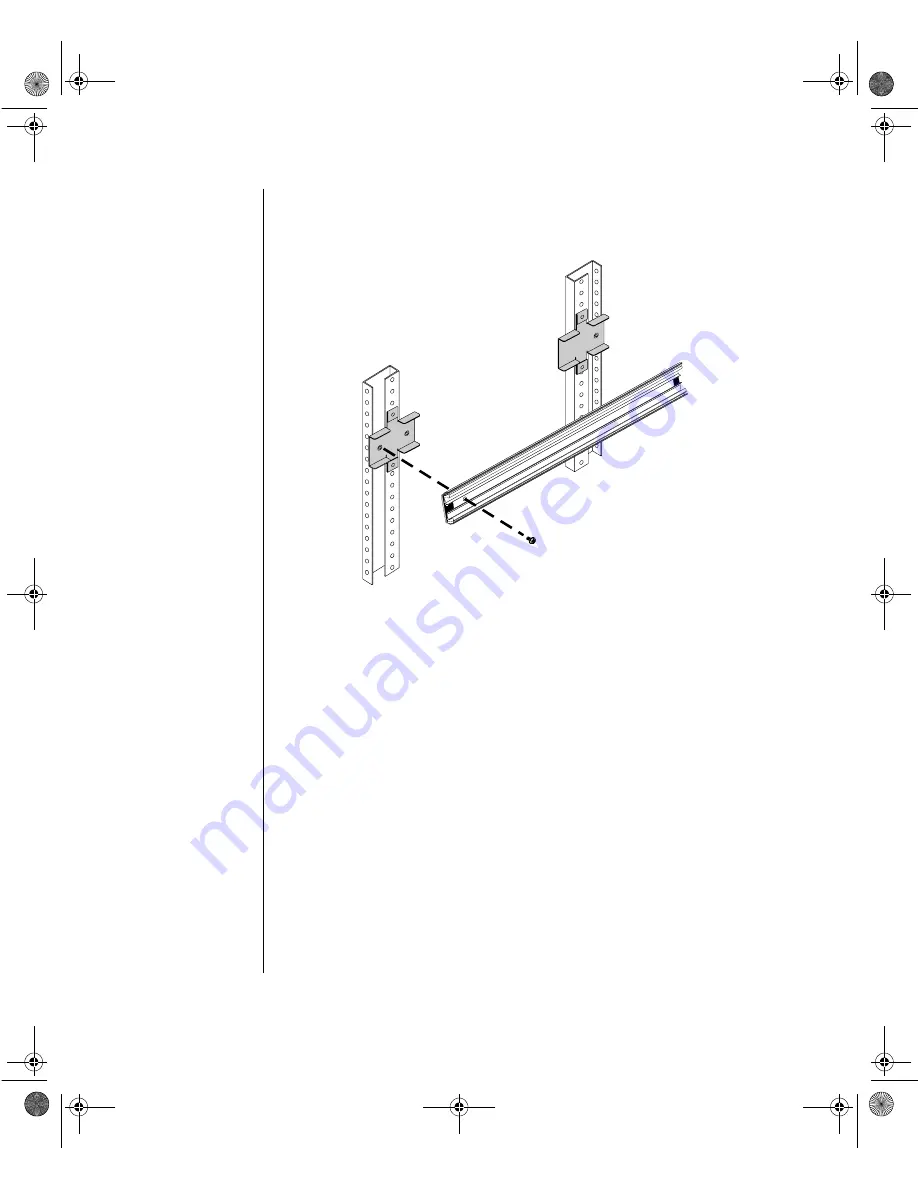
Mount the rail in the rail brackets using a single screw for each end of 
the rail. See Figure 6.

Figure 6: Attaching the Cabinet Mounting Rails

8.

To secure the rear of the rail, slide the inner rails forward to gain 
access to the mounting holes. The latch may lock the rail into place. 
Release the latch to allow the rails to slide freely. To secure the front of 
the rail, slide the inner rail so that the opening aligns with the 
mounting holes. Verify that the inner rails slide freely.

2953.book  Page 10  Monday, June 15, 1998  11:27 AM

Summary of Contents for ALR 8200R

Page 1: ...DE R0 6 98 In our effort to use nature s resources efficiently and wisely we print all manuals on recycled papers that meet the minimum requirements established by the Federal EPA in its guidelines for recycled paper products 2953 book Page i Monday June 15 1998 11 27 AM ...

Page 2: ...nc Intel Intel Inside logo and Pentium are registered trademarks and MMX is a trademark of Intel Corporation Microsoft MS MS DOS and Windows are trademarks or registered trademarks of Microsoft Corporation All other product names mentioned herein are used for identification purposes only and may be the trademarks or registered trademarks of their respective companies Copyright 1998 Advanced Logic ...

Page 3: ...Peripherals 13 Using an AutoSwitcher with Multiple System Drawers 14 Powering Up the System 16 Quick Check 16 Completing the Installation 18 System Features 21 Basic Features 22 Front Panel 24 Dual Redundant 400 Watt Power Supplies 24 3 5 inch Diskette Drive 25 CD ROM Drive 25 LED Indicators 26 Buttons 26 RAID Cage Bay 26 Rear Panel 27 I O Ports 27 Power Connectors 28 Expansion Slot Cover Plates 2...

Page 4: ...cessor Speed 45 System Memory 46 Configuring Your Memory 46 Installing DIMMs 47 Adapter Cards 49 Storage Bays 51 Removing the Drive Bay Assembly 52 Removing the 5 25 inch Device 53 Installing a 5 25 inch Device 54 3 5 inch Devices 55 RAID Bay 58 BIOS Setup 65 About the BIOS Setup Utility 66 Using the BIOS Setup Utility 67 Main Menu Screen 68 Advanced Menu Screen 72 Security Menu Screen 81 Power Me...

Page 5: ...s 99 Types of Viruses 99 Virus Contamination 99 Protecting Your System 100 Virus Prevention 100 Troubleshooting Checklist 102 Verifying Your Configuration 102 Troubleshooting Guidelines 102 CD ROM Problems 103 Hard Disk Problems 104 Memory Processor Problems 105 Modem Problems 106 Peripheral Adapter Problems 107 Printer Problems 109 System Problems 110 Video Problems 112 Error Messages 114 Setting...

Page 6: ...ettings 121 Active Termination 122 Auto Start Delay Start 122 Cluster Option 123 Regulatory Compliance Statements 125 FCC Notice 126 Industry Canada Notice 127 CE Notice 127 VCCI Notice 128 Australia New Zealand Notice 128 Index 129 2953 book Page vi Monday June 15 1998 11 27 AM ...

Page 7: ...Preface Contents About This Guide viii Conventions Used in this Guide ix 2953 book Page vii Monday June 15 1998 11 27 AM ...

Page 8: ...onnectors and arranging your workspace Chapter 3 Components describes the major components included in the system Chapter 4 BIOS Setup describes the BIOS setup utility and provides detailed descriptions of the screens fields and options within that program Chapter 5 Maintaining and Cleaning Your System provides instructions on standard maintenance tasks and procedures for cleaning the exterior por...

Page 9: ...it must be pressed simultaneously Setup Commands to be entered as well as messages that appear on your monitor are printed in ARIAL NARROW font System User s Guide Names of publications and files are italicized Run Options to select are boldfaced Sidebars Sidebars denote critical information such as warnings important information and important notes Note This is an example of an important note tha...

Page 10: ...x Gateway ALR 8200R User s Guide 2953 book Page x Monday June 15 1998 11 27 AM ...

Page 11: ...ions 3 Opening the System 3 Closing the System 5 Installing the Processor Drawer 7 Inspecting the Contents 7 Installing the Processor Drawer in the Rack 8 Connecting Peripherals 13 Powering Up the System 16 Quick Check 16 Completing the Installation 18 2953 book Page 1 Monday June 15 1998 11 27 AM ...

Page 12: ... install the processor drawer in your rack system and have it operating This section shows you how to Access the system interior Install the processor drawer Connect the monitor and keyboard Power up the system Carefully read and follow these instructions to ensure that the system operates correctly 2953 book Page 2 Monday June 15 1998 11 27 AM ...

Page 13: ...ck of the power supply fan located on the back of the case 4 UNPLUG ALL CORDS FROM WALL OUTLET 5 Remove the system case cover Static Electricity Precautions Avoid static causing surfaces such as plastic and styrofoam in your work area Remove the parts from their antistatic bags only when you are ready to use them Do not lay parts on the outside of antistatic bags since only the inside provides ant...

Page 14: ...retainers 90 degrees counter clockwise Figure 1 Opening the Top Cover 3 Lift the lid covering the front portion of the system 1 Disconnect both power cords and power down the system 2 On the top front of the system turn each of the three slotted retainers 90 degrees counter clockwise Opening the Top Cover Removing the Top Cover Warning This product contains hazardous moving parts Ensure that the c...

Page 15: ...and the four screws from the back of the top cover 4 Remove the top cover Figure 2 Removing the Top Cover Closing the System Before closing the system verify that all connectors and boards are properly installed and firmly seated 2953 book Page 5 Monday June 15 1998 11 27 AM ...

Page 16: ...ly 1 Position the top cover on the chassis aligning the three holes on each side and four holes in back 2 Reinstall the screws removed when the top cover was removed three on each side and four in back 3 Turn the three slotted retainers 90 degrees clockwise to secure the front portion of the top cover in place Figure 3 Reinstalling the Top Cover Replacing the Top Cover 2953 book Page 6 Monday June...

Page 17: ...drawer is configured for AC operation protect it against AC line spikes by using a 3 prong 115 V or 230 V depending on the voltage supplied in your locality and an AC surge control outlet station The system may require two separate AC outlets one per power supply Inspecting the Contents Unpack the carton and inspect the contents Standard systems include the following items System Drawer Power Cabl...

Page 18: ...remove the side rails from the mounting rails by depressing the retention clips and sliding them off 2 Mount the side rails on the processor drawer with the twelve 12 screws provided The retention clips should go toward the rear of the cabinet Figure 4 Installing the Mounting Rails Installing the Mounting Rails Note Drawer heights are measured in U s Each U is 1 75 inches measured vertically on th...

Page 19: ...Cabinet 4 Mark the screw hole locations onto the vertical mounting strips in the cabinet as shown on the template The marks will locate the mounting holes of the rail brackets and front panel 5 Attach the front bracket to the front cabinet vertical mounting strip using two screws Attach the rear bracket to the rear cabinet vertical mounting strip 6 Repeat steps 4 and 5 to mount the second rail bra...

Page 20: ...To secure the rear of the rail slide the inner rails forward to gain access to the mounting holes The latch may lock the rail into place Release the latch to allow the rails to slide freely To secure the front of the rail slide the inner rail so that the opening aligns with the mounting holes Verify that the inner rails slide freely 2953 book Page 10 Monday June 15 1998 11 27 AM ...

Page 21: ...ock the rails in the out position 2 Lift the processor drawer to the same height as the mounting rails and align the rails on the drawer with the cabinet mounting rails See Figure 7 Figure 7 Installing the Processor Drawer Mounting the Processor Drawer in the Cabinet Note The processor drawer is heavy To prevent injury and possible damage to the equipment we recommended that you have assistance wh...

Page 22: ...wer rails lock See Figure 8 Figure 8 Cabinet Rail Retaining Latches 4 Press the latches on both side rails of the processor drawer and push the drawer into the cabinet until the front panel touches the vertical mounting rails The drawer may move reluctantly at first However it should move smoothly without binding or restriction thereafter 2953 book Page 12 Monday June 15 1998 11 27 AM ...

Page 23: ...ls 1 Power off all drawers and devices in the cabinet prior to attaching any of the system drawer cables 2 Verify that the system drawer power switch is in the OFF position 3 Connect controller and data cables to their respective devices as appropriate e g SCSI cables to QHS Drawer or Parallel cables to printer etc Connecting Peripherals 2953 book Page 13 Monday June 15 1998 11 27 AM ...

Page 24: ...cable to an appropriate power source 7 Verify that the Voltage Selector Switches on the power supplies are set for the proper voltage 115V or 230V 8 Connect the system power cables to the power input connectors 9 Connect the other end of the system power cables to the appropriate power sources Using an AutoSwitcher with Multiple System Drawers Multiple system drawers installed in the same system c...

Page 25: ...eyboard the mouse and the monitor are plugged into the AutoSwitcher connecting the system drawers to an AutoSwitcher requires extender cables Refer to Figure 10 for example connection details Figure 10 Connecting to an AutoSwitcher 2953 book Page 15 Monday June 15 1998 11 27 AM ...

Page 26: ...m functions until the error can be corrected usually through the BIOS Setup In the rare case of a fatal error contact your Technical Support for field service support Quick Check If your system does not operate correctly re read the instructions for the procedure s you have performed If an error occurs within an application consult the documentation supplied with the software This section identifi...

Page 27: ...following guidelines in mind Never remove the system cover while the system is powered on Do not attempt to open the monitor it is extremely dangerous Even if the monitor power is disconnected stored energy within the monitor components can cause a painful or harmful shock If a peripheral such as the keyboard mouse drive or printer does not appear to work ensure that all connections are secure If ...

Page 28: ...aintenance because the cables are kept neatly out of the way 1 Position the cable retractor to the rear side of the cabinet so that the mounting holes on both retractor and cabinet are aligned 2 Using two screws secure the cable retractor to the mounting holes on the rear of the system drawer Figure 11 Installing a Cable Retractor Installing a Cable Retractor 2953 book Page 18 Monday June 15 1998 ...

Page 29: ...igned with tie holes to permit installation of tie wraps Figure 12 Routing Cable on the Cable Retractor 3 Leave enough slack in the cables to allow them to flex when the drawer is pulled out 4 Check the cables for tight spots while the drawer is being pulled forward and pushed back into place Check for stress points especially at the bends in the cable retractor and where the cable retractor is mo...

Page 30: ... System Physical security for the system is dependent upon the security provided by the cabinet 1 Close the rear door of the system cabinet and lock if desired 2 Push the system drawer back until its front panel presses against the vertical mounting rails in the cabinet Secure the drawer with four screws 3 Close the front door and lock if desired Securing the System 2953 book Page 20 Monday June 1...

Page 31: ...AID Cage Bay 26 Rear Panel 27 I O Ports 27 Power Connectors 28 Expansion Slot Cover Plates 28 System Board 29 Chassis Fans 30 Power Connectors 30 Front Panel Connectors 31 Drive Controllers and Connectors 32 Server Management Connectors 33 System Jumpers 34 Battery 35 Expansion Slots 35 I O Connectors 35 Processor Subsystem 36 Memory 37 2953 book Page 21 Monday June 15 1998 11 27 AM ...

Page 32: ...redundant array of inexpensive drives RAID port one shared PCI ISA and one ISA slot Integrated 32 bit dynamic random access memory DRAM PCI Graphics Cirrus Logic GD54M30 with 2 MB DRAM Integrated 10 100 Ethernet port using an RJ 45 connector Integrated PCI Ultra2 small computer system interface SCSI Adaptec 7890 with two 68 pin connectors dual channel Ultra direct memory access DMA PCI integrated ...

Page 33: ...and report the operating status of the system and its devices processors power supplies RAM ambient temperatures voltages and fan operation For further information about the InforManager refer to the InforManager User s Guide Phoenix upgradable Flash basic input output system BIOS Year 2000 Ready 2953 book Page 23 Monday June 15 1998 11 27 AM ...

Page 34: ...er from one or two 400W power supplies which are removable through the front of the system drawer The system ships with a single power supply module The second module is available as an option A Power supply fault LED H Hard disk activity LED B Power supply module 1 I System reset button C Power supply switch J ECC reset button D Power supply voltage selection switch K ECC error LED E Power supply...

Page 35: ...re the LED shines amber If the module is not receiving power or has failed completely the light is off Power On Switch Each power supply module is equipped with a power on switch that allows you to turn off the module before removing it or during maintenance Voltage Selection Switch A voltage selection switch is located on the upper front of each power supply module These switches must be set for ...

Page 36: ... on the drives see Installing an Internal 3 5 inch Device on page 57 and Replacing Hot Swapping a Drive on page 63 Table 1 Front Panel LED Indicator Lights LED Meaning When Lit Power The system is on Hard Disk Controller Activity The hard disk is being accessed ECC Error An ECC error has occurred Table 2 Front Panel Buttons Switch Function Power Turns the system ON or OFF Reset Allows you to reset...

Page 37: ...nector J Dual USB ports C Power connectors K Ethernet port D Serial Port 1 L Primary PCI slots E Parallel port M Secondary PCI slots F Serial port 2 N Shared PCI RAIDport slot G Keyboard port O Shared PCI ISA slot H Mouse port P ISA slot Port Definition 68 pin SCSI Connector Provides an external SCSI connection for use with a Tape Storage drawer or QHS Storage drawer RackBus Connector Allows the p...

Page 38: ... and 2 These are high speed serial ports which use the First In First Out FIFO protocol If you have a serial mouse connect it to Serial Port 1 COM1 Other serial devices such as serial printers or modems can also be connected these ports Mouse Port This port supports any mouse with a miniature circular DIN mini DIN connector Keyboard Port This port supports any keyboard with a miniature circular DI...

Page 39: ... connectors L Reset connector C Standby 3 3 V power connector M External HDD connector D Soft power connector N HDD LED connector E P5 fault reset connector O Server management connector F Power supply auxiliary connector P User NMI connector G Chassis fan connector Q EDC reset connector H Secondary IDE connector R Chassis fan connector I Primary IDE connector S Cover intrusion switch connector J ...

Page 40: ...down This feature is not implemented in this system U External boot ROM connector AM Mouse port keyboard port V I2 C connector AN Serial port 2 W SCSI B connector AO Parallel port X SCSI A connector AP Serial port 1 Y Clear CMOS jumper AQ Processor connector 1 Z Battery AR Processor connector 2 AA ISA slot 2 AS DIMM connectors x4 AB ISA slot 1 shared w secondary PCI slot 4 AT DIMM bank A AC Second...

Page 41: ...lt condition persists the processor fault LED will turn back on Reset Connector The reset connector provides the connection of the reset button from the front panel External HDD Connector The external hard drive connector allows you to connect a cable from an external hard drive to the system board to allow the hard drive activity LED and system monitoring hardware to recognize the external drive ...

Page 42: ...so provided Hard Drive Controller and Connectors This is an integrated dual channel Ultra DMA PCI IDE integrated drive electronics interface with two IDE connectors capable of controlling up to four IDE devices and supporting paging input output PIO Modes 0 4 Ultra direct memory access DMA provides faster access to IDE devices that are Ultra DMA compliant while maintaining support for IDE devices ...

Page 43: ...ted SCSI peripherals per channel for as many as 30 devices As many as seven 8 bit devices can be installed on each channel Multi threading support for up to 255 simultaneous I O tasks Advanced SCSI I O cell ensuring data integrity by automatically and continuously adjusting slew rate to compensate for SCSI bus loading Driver support for all major operating systems Server Management Connectors The ...

Page 44: ... this section Do not change any jumper unless it is necessary to configure the system In some cases changing the settings of reserved jumpers can cause damage to the system board Clear CMOS Jumper This jumper allows you to clear the CMOS memory You should only do this if you cannot access the normal methods of modifying the CMOS and modifications to the CMOS are necessary Clearing CMOS memory retu...

Page 45: ...ed on the back panel of the system Figure 16 shows the connectors and the table below provides the key to the figure Figure 16 I O Connectors A Parallel Port E Mouse Port B Serial Port 1 F Video Port C Serial Port 2 G Dual USB Ports D Keyboard Port H RJ45 Ethernet Port with LED indicators Caution There is a danger of explosion if the battery is incorrectly replaced Replace the battery only with th...

Page 46: ... serial ports One bi directional ECP EPP parallel port One VGA video port One PS 2 style mouse port One PS 2 style keyboard port One RJ 45 Ethernet connector with two LED indicators The green LED indicates a communication link has been established with the network and the yellow indicator shows that the communication is occurring at 100 Mbps when on and at 10Mbps when off Processor Subsystem The s...

Page 47: ...des a fan connect it to the correct fan connector Voltage Regulator Modules Each processor must have a dedicated voltage regulator module VRM that adjusts the voltage supplied to the processor The VRM for the first processor CPU 1 is embedded on the system board The VRM for the second processor CPU 2 is placed in the provided connector when the second processor is installed Memory The system comes...

Page 48: ...38 Gateway ALR 8200R User s Guide 2953 book Page 38 Monday June 15 1998 11 27 AM ...

Page 49: ...2 44 Changing the Processor Speed 45 System Memory 46 Configuring Your Memory 46 Installing DIMMs 47 Adapter Cards 49 Storage Bays 51 Removing the Drive Bay Assembly 52 Removing the 5 25 inch Device 53 Installing a 5 25 inch Device 54 3 5 inch Devices 55 RAID Bay 58 2953 book Page 39 Monday June 15 1998 11 27 AM ...

Page 50: ...nd processor This chapter provides procedures to assist you in installing some of these options For more information about available options for your system contact your reseller or Gateway Sales Your system supports a second processor to further enhance system performance Processor Upgrade kits are readily available at your reseller Figure 17 Pentium II Processor 2953 book Page 40 Monday June 15 ...

Page 51: ...performance 1 If replacing an existing processor remove the processor retaining bar from the connector by removing the two screws that secure it 2 Gently pull out the processor cartridge from the support bracket and save the it for future use Figure 18 Removing the Existing Pentium II Processor Installing a Pentium II Processor 2953 book Page 41 Monday June 15 1998 11 27 AM ...

Page 52: ...t processor connector 2 Figure 19 Removing the Terminator Card 4 Remove the new processor cartridge from its protective packaging 5 Align the new processor cartridge with the guides on the support bracket and push the cartridge into the processor connector 2953 book Page 42 Monday June 15 1998 11 27 AM ...

Page 53: ...d lock it into place by replacing the retaining bar you removed in step 1 7 If you upgraded processor 1 then go directly to Changing the Processor Speed on page 45 If you upgraded processor 2 then continue on to the next section Installing A VRM for Processor 2 on page 44 2953 book Page 43 Monday June 15 1998 11 27 AM ...

Page 54: ...ket is provided to accommodate the VRM for processor 2 When you install a second processor you must also install a VRM 1 Open the system and locate the VRM socket on the system board See System Board on page 29 Figure 21 Installing a VRM Installing a VRM Note The VRM for processor 1 is integrated on the system board Install a VRM only if installing a second processor 2953 book Page 44 Monday June ...

Page 55: ...e the processor s you must change the processor clock speed jumper settings as well The following table shows the proper jumpers settings for the processor you have selected After you have changed the jumper settings reinstall the top cover and power up the system Note Both the VRM and the socket are keyed to prevent improper connection Warning Running the processor at a speed higher than it is ra...

Page 56: ...MB 2x72 16MB 2x72 16MB 96 4x72 32MB 4x72 32MB 2x72 16MB 2x72 16MB 128 16x72 128MB 128 8x72 64MB 8x72 64MB 128 8x72 64MB 4x72 32MB 4x72 32MB 128 8x72 64MB 4x72 32MB 2x72 16MB 2x72 16MB 192 16x72 128MB 8x72 64MB 192 16x72 128MB 4x72 32MB 4x72 32MB 192 16x72 128MB 4x72 32MB 2x72 16MB 2x72 16MB 192 8x72 64MB 8x72 64MB 8x72 64MB 192 8x72 64MB 8x72 64MB 4x72 32MB 4x72 32MB 256 32x72 256MB 256 16x72 128M...

Page 57: ... larger capacity DIMMs 1 Remove the top cover 2 If upgrading an existing memory module remove the DIMM by pushing the retaining latches away from each other Pull out the DIMM and store it for future use Figure 22 Removing an Original DIMM Installing DIMMs 2953 book Page 47 Monday June 15 1998 11 27 AM ...

Page 58: ...the DIMM into place by pushing the retaining latches towards each other 6 Repeat steps 3 through 5 to install additional DIMMs 7 Reinstall the top cover as previously described and power up the system Note The DIMM units are keyed to align with the DIMM sockets Warning For safety reasons the top cover must be closed and secured while the system is running 2953 book Page 48 Monday June 15 1998 11 2...

Page 59: ...ent must be plugged into a grounded outlet Always hold a card or board by its edges Do not rest the board on any static generating surface such as carpeting 1 Remove the top cover 2 Locate an available expansion slot ISA or PCI on the system board 3 Use a Phillips screwdriver to remove the screw that secures the cover plate of the slot you have selected Save the screw Installing Expansion Cards 29...

Page 60: ...ns with the card guide See Figure 24 Figure 24 Installing an Adapter Card 5 Secure the card with the screw you removed in step 2 Double check the card making sure it is seated correctly 6 Reinstall the top cover and power up the system Warning For safety reasons the top cover must be closed and secured while the system is running 2953 book Page 50 Monday June 15 1998 11 27 AM ...

Page 61: ... inch device or any 3 5 inch device with a special mounting bracket RAID bay which supports up to three 3 5 inch LVDSCA drives Refer to the specific section that corresponds to the type of device you are installing Figure 25 Additional Device Options A Internal 3 5 inch drive mounts D RAID Cage three 3 5 inch LVD SCA drives B 3 5 inch diskette drive installed E 400 W hot swap power supplies C 5 25...

Page 62: ... inch CD ROM drive and the 3 5 inch drives in the RAID Cage bay The instructions for removing these drives will refer to this section 1 Turn the system power off 2 Open the system by removing the top cover 3 Unplug the data and power cables to all devices in the drive bay assembly 4 Remove the six screws that secure the drive bay assembly to the bottom of the drawer Figure 26 Removing the Drive Ba...

Page 63: ...5 inch drive bay This bay normally contains a CD ROM drive If you want to replace the CD ROM drive with another device you must first remove the existing CD ROM drive 1 Turn the system power off 2 Open the system by removing the top cover 3 Remove the drive bay assembly See Removing the Drive Bay Assembly on page 52 4 Press the tabs on the front end of the drive rails in toward the center of the d...

Page 64: ...stem power off 2 Open the system by removing the top cover 3 If no 5 25 inch device is currently installed remove the metal RF shield that protects the 5 25 inch device bay 4 Attach mounting rails to the 5 25 inch device 5 From the front of the chassis insert the drive into the bay Figure 28 Installing a 5 25 inch Drive 6 Connect the device cable to the device making sure that pin 1 on both cable ...

Page 65: ...mation in BIOS Setup then reboot the system 3 5 inch Devices The system drawer supports as many as six 3 5 inch devices The majority of these devices are expected to be hard drives However the system ships with a 3 5 inch diskette drive as well Replacing the 3 5 inch Diskette Drive The system ships with a standard 1 44 MB capacity 3 5 inch diskette drive If this drive fails and must be replaced fo...

Page 66: ...the system board see Figure 15 on page 29 10 Connect the drive cable making certain to match pin 1 on both connectors On most standard cables pin 1 is designated by a colored wire on the cable In some cases the connector is keyed 11 Connect the drive to the power supply using an available power connector 12 Reinstall the top cover and power up the system 13 Enter the BIOS Setup program by pressing...

Page 67: ...t are not accessible from the outside of the system These brackets are intended for mounting 3 5 inch hard drives or similar devices 1 Turn the system power off 2 Open the system by removing the top cover 3 Install the mounting brackets 2 onto the device with the screws supplied Figure 30 Installing an Internal 3 5 inch Device Installing an Internal 3 5 inch Device 2953 book Page 57 Monday June 15...

Page 68: ...drive information in BIOS Setup then reboot the system RAID Bay The RAID bay is a reliable fault tolerant network storage solution that supports RAID levels 0 1 and 5 and accommodates up to three 1 inch or 1 6 inch high 3 5 inch LVD SCA drives For optimum operation use only approved RAID Ready drives with the RAID bay The RAID bay allows you to easily configure a reliable RAID subsystem Drives are...

Page 69: ...nnector fast wide cable to the controller Refer to the following page for jumper locations on the RAID bay backplane Figure 31 RAID Bay Backplane A DC power G 8 bit terminator B 50 pin SCSI connector H 68 pin SCSI connector C Auto start delay start I Termination power D 16 bit active terminator J Cluster option E Lower SCSI ID address or 0 1 2 or 4 5 6 K Fan connector F Upper SCSI address 8 9 10 o...

Page 70: ...er for instructions on how to properly terminate your controller Terminate the other end of the SCSI subsystem by setting JP8 and or JP3 on the RAID Cage backplane These jumpers provide active termination on the SCSI bus JP6 provides termination power for the 8 bit 50 pin connector at the top to the RAID cage and JP3 provides active termination for the 16 bit 68 pin Ultra2 Wide SCSI connector Acti...

Page 71: ...nstructions in the documentation that came with your SCSI controller for more information on setting up the SCSI controller 5 Install the hard disk drives as shown in Installing the Drives on page 61 Installing the Drives The RAID bay accommodates up to three LVD SCA drives Drives are mounted on a rail system that allows quick and easy installation and hot swapping 1 Label the SCSI Channel and the...

Page 72: ...ign the drive rails with the drive cage guides 4 Slide the drive in until it makes contact with the connector at the rear of the cage Figure 33 Installing an SCA Drive 5 Press firmly until the drive seats in the connector The locking tabs lift away from the face of the front panel and swing inward when the drive is seated 2953 book Page 62 Monday June 15 1998 11 27 AM ...

Page 73: ... the matching SCSI ID Number Label provided with the new drive and affix it to the front of the new device 5 If replacing the failed drive while the system is running place the failed drive off line first This may be accomplished automatically if your system is set up for enhanced RAID level 5 operation Otherwise you must run the software 6 Remove the failed drive by swinging the locking tabs outw...

Page 74: ...64 Gateway ALR 8200R User s Guide 2953 book Page 64 Monday June 15 1998 11 27 AM ...

Page 75: ... Setup Utility 66 Using the BIOS Setup Utility 67 Main Menu Screen 68 Advanced Menu Screen 72 Security Menu Screen 81 Power Menu Screen 83 Boot Menu Screen 84 Exit Menu Screen 86 Updating the BIOS 87 2953 book Page 65 Monday June 15 1998 11 27 AM ...

Page 76: ...as a guide so that you can make changes to your system s BIOS when necessary Many of the screen examples that you will see in this chapter are identical to what you see on your monitor however you may have a system with a newer BIOS version than the one described in this manual In that case some of the examples may differ somewhat from what you see but the screens will be similar enough that you w...

Page 77: ...n a submenu Back Press ESC to back out of any field Next and Previous Item Press the up arrow or down arrow keys to move to the next or previous menu item Select Menu Use the left arrow and right arrow keys to move between the six main menus Main Advanced Security Power Boot and Exit Change Values Toggles through available options for selected item ENTER Select Sub Menu Pressing ENTER when a sub m...

Page 78: ...r clock System Date lets you set the system date Legacy Diskette A allows you to select the type of diskette drive installed as drive A The options are 360 kB 5 1 2 MB 5 720 kB 3 1 44 1 25 MB 3 2 88 MB 3 NOT INSTALLED and DISABLED Legacy Diskette B allows you to select the type of diskette drive installed as drive B The options are 360 kB 5 1 2 MB 5 720 kB 3 1 44 1 25 MB 3 2 88 MB 3 NOT INSTALLED ...

Page 79: ...e Setup Screen on page 70 Secondary Master opens the Secondary Master screen to permit you to setup the secondary master hard disk drive Details of this screen are provided in the section Hard Disk Drive Setup Screen on page 70 Secondary Slave opens the Secondary Slave screen to permit you to setup the secondary slave hard disk drive Details of this screen are provided in the section Hard Disk Dri...

Page 80: ...previously defined drive types and sizes These values only apply to older drives generally less than 200 MB in size User Selecting this option brings up a sub menu where you can enter the CYLINDERS HEADS SECTORS and MAXIMUM CAPACITY of the drive you are configuring These values are generally available from the documentation for the drive or the drive label itself Auto Selecting this option automat...

Page 81: ...ption causes Logical Block Addressing to be used in place of Cylinders Heads and Sectors The options are ENABLED and DISABLED 32 Bit I O enabling this option allows 32 bit communication between the processor and the IDE controller The options are ENABLED and DISABLED Transfer Mode selects the method for moving data to and from the drive The options listed are those supported by the drive and the p...

Page 82: ... compatible with Plug and Play The options are Yes and No Reset Configuration Data selecting Yes causes the system to clear its configuration data and automatically configure all PnP devices at bootup Selecting No causes the system to use the existing configuration information Use Multiprocessor Specification this field configures the multiprocessor specification for compatibility reasons Specific...

Page 83: ...on Cache Memory Screen on page 80 Advanced Chipset Control opens the advanced chipset control screen which contains a single field The field is ECC Config which allows you to set the extent of error checking and correction that the system uses The options for this field are Disabled EC ECC and ECC Scrub Embedded PCI SCSI Channel A enabling turns on channel A of the optional integrated SCSI adapter...

Page 84: ...ion screen This screen allows the user to reserve blocks of upper memory for use by legacy ISA devices Details of this screen are provided in the section Memory Reservation Screen on page 75 IRQ Reservation opens the IRQ Reservation screen This screen allows the user to reserve IRQs for use by legacy ISA devices Details of this screen are provided in the section IRQ Reservation Screen on page 76 2...

Page 85: ...lected from the resource configuration screen It allows you to reserve a block of memory for ISA devices Figure 39 Memory Reservation Screen XXXX XXXX the specified area of upper memory may be reserved for use by legacy ISA devices Options are Available and Reserved 2953 book Page 75 Monday June 15 1998 11 27 AM ...

Page 86: ...lect IRQ Reservation from the advanced menu screen It allows you to manually reserve IRQs for specific devices Figure 40 IRQ Reservation Screen IRQx the specified IRQ may be reserved for use by legacy ISA devices Options are Available and Reserved 2953 book Page 76 Monday June 15 1998 11 27 AM ...

Page 87: ...e optional addresses available Interrupt displays the current interrupt for integrated Serial Port A Using the or key displays the optional addresses available Serial Port B options include Enabled Disabled and Auto Base I O Address displays the base I O address for integrated Serial Port B Using the or key displays the optional addresses available Interrupt displays the current interrupt for inte...

Page 88: ...ey displays the optional addresses available Interrupt displays the current interrupt for the integrated Parallel Port Using the or key displays the optional addresses available DMA Channel displays the current DMA channel used by the Parallel Port Using the or key displays the optional channels available Floppy Disk Controller controls the integrate diskette controller Options include Enable and ...

Page 89: ...Key Click options are Enable and Disable Enable causes an audible click when each key is pressed Keyboard Auto Repeat Rate determines the rate at which a character repeats if a key is held down Options are 2 sec 6 sec 10 sec 13 3 sec 18 5 sec 21 8 sec 26 7 sec and 30 sec Keyboard Auto Repeat Delay determines the amount of delay before a pressed key repeats Options are 1 2 sec 3 4 sec and 1 sec 295...

Page 90: ...ea controls the caching of the system BIOS area Options are Uncached or Write Protect Cache Video BIOS Area controls the caching of the video BIOS area Options are UNCACHED or Write Protect Cache Base 0 512K controls caching of the first 512K of base memory Options are Write Back Write Through or Uncached Cache Base 512K 640K controls caching of the 512K through 640K area of base memory Options ar...

Page 91: ...bled or Disabled Security Menu Screen This screen allows you to set system security characteristics Figure 44 Security Menu Screen Supervisor Password displays status of administrative password Options are Clear no password entered and Set a password has been established User Password displays status of user password Options areClear no password entered and Set a password has been established 2953...

Page 92: ...d used to control access to the system at boot If the user password has already been set you must enter the current password before you are able to enter and verify the new password Password on Boot when this option is enabled the system prompts the user for a password before booting the system Fixed Disk Boot Sector options for this field are Normal and Write Protect which protects the boot secto...

Page 93: ...stem enters its low power state Auto Suspend Timeout opens a menu in which you can select the number of PCI clock cycles within which a PCI card must be guaranteed access to the PCI bus Device specified Monitoring options are Enabled and Disabled When enabled activity on the device specified will keep the system awake Wake on Embedded LAN The options are Enabled and Disabled When enabled the syste...

Page 94: ...ignates the device that the system polls second upon boot up Options include Diskette Drive Hard Drive Removable Devices ATAPI CD ROM Drive and Network Boot Third Boot Device designates the device that the system polls third upon boot up Options include Diskette Drive Hard Drive Removable Devices ATAPI CD ROM Drive and Network Boot Fourth Boot Device designates the device that the system polls fou...

Page 95: ...e on this list If no operating system is found the system tries the next drive listed until an operating system is found Use the up and down arrows to select a device then press or to move it up or down the list Removable Devices displays a list of available removable devices The system assigns drive letters to these devices in the order displayed To change the sequence and drive letter of a devic...

Page 96: ... entered The next time you boot the system the BIOS configures your system using the old settings Load Setup Defaults displays the setup defaults in cases where the settings have been corrupted or incorrectly modified Press F1 to resume the boot or F2 to run the BIOS Setup with the ROM default values already loaded into the menus Discard Changes restores the CMOS settings previously entered not th...

Page 97: ...ncompress the contents of the BIOS file you downloaded and copy the contents onto a bootable disk 6 Place the bootable disk containing the BIOS files into drive A then restart the system with the disk in the drive The BIOS Setup program starts 7 Press ENTER to go to the Main menu 8 Select Update Flash Memory From a File and press ENTER 9 Select Update System BIOS and press ENTER 10 Press TAB to se...

Page 98: ...CMOS values back to defaults using the F5 key or the correct values from your earlier configuration the system may function erratically You may encounter a CMOS checksum error or other problem after the system restarts If so try turning the system off and then restarting CMOS checksum errors require that you enter BIOS Setup check your settings save your settings and exit setup 2953 book Page 88 M...

Page 99: ...em Contents Maintaining Your System 90 Maintaining your Hard Drive 90 Cleaning The System 93 Cleaning the Mouse 93 Cleaning the Keyboard 94 Cleaning the Monitor Screen 94 Cleaning the Monitor Case 94 2953 book Page 89 Monday June 15 1998 11 27 AM ...

Page 100: ...depending on how often and how much you use your computer 1 In Windows 95 Click on the Start button Then click on Programs then Accessories then System Tools and then ScanDisk The ScanDisk window opens In Windows NT Scandisk is accessed through the Tools tab of the drive s Properties sheet 2 In the ScanDisk window click on the drive you want to scan 3 If you only want to check your files and folde...

Page 101: ...indow select another drive then go to Step 6 8 When you are finished using ScanDisk click on Close Using Disk Defragmenter Windows NT does not include Disk Defragmenter The Disk Defragmenter program helps maintain the integrity of your hard drive by rearranging files so that unused space on your hard drive is not scattered around the drive but is contained in one contiguous area on the disk You ma...

Page 102: ...click OK A dialog box opens showing the progress of the defragmentation When defragmentation is complete a dialog box opens and asks you if you want to quit the Disk Defragmenter program 3 If you are finished defragmenting the drives in your system click Yes If you have more drives to defragment click No and return to Step 2 2953 book Page 92 Monday June 15 1998 11 27 AM ...

Page 103: ...our mouse right side up The gray mouse ball should drop into your hand If it doesn t gently shake the mouse until the ball drops out of the socket 4 Once the mouse ball is free use adhesive tape to pick up any dust or lint on its surface and wipe away dirt or lint inside the mouse ball socket You can also blow into the socket to remove dirt and lint If foreign matter is trapped inside the socket o...

Page 104: ...ernight before trying to use it again If it fails to work after draining replace the keyboard Cleaning the Monitor Screen Use a soft cloth and window cleaner to clean the monitor screen Squirt a little cleaner on the cloth never directly on the screen and wipe the screen with the cloth Cleaning the Monitor Case Always shut down the system and other peripherals before cleaning any components Use a ...

Page 105: ...g Your System 100 Virus Prevention 100 Troubleshooting Checklist 102 Verifying Your Configuration 102 Troubleshooting Guidelines 102 CD ROM Problems 103 Hard Disk Problems 104 Memory Processor Problems 105 Modem Problems 106 Peripheral Adapter Problems 107 Printer Problems 109 System Problems 110 Video Problems 112 Error Messages 114 2953 book Page 95 Monday June 15 1998 11 27 AM ...

Page 106: ...e correctly and completely If an error occurs in an application consult the documentation supplied with the software This section identifies solutions to common problems If the suggestions in this chapter do not resolve your problem call Technical Support Note Do not return any equipment without obtaining a Return Material Authorization RMA number 2953 book Page 96 Monday June 15 1998 11 27 AM ...

Page 107: ...is plug will only fit into a grounded power outlet This is a safety feature If you are unable to insert the plug into the outlet contact your electrician to replace the outlet Do not walk on the power cord or allow anything to rest on it If you use an extension cord with this system make sure the total ampere ratings on the products plugged into the extension cord do not exceed the extension cord ...

Page 108: ...nstructions are followed d The system was dropped or the cabinet is damaged e The system s performance changes Important The system power cord serves as the main disconnect for the computer The wall outlet must be easily accessible by the operator 2953 book Page 98 Monday June 15 1998 11 27 AM ...

Page 109: ... macro files of programs such as word processing and spreadsheet programs Bootviruses attach themselves to a boot record master boot FAT or partition table Multipartite viruses are both program and boot infectors Virus Contamination There are many ways a virus can spread and infect your system However a virus is inactive until the infected program is executed or a boot record is read Thereafter th...

Page 110: ...virus program Next reboot your system as follows shut the system down then turn it off for at least 15 seconds before turning it back on This is the only way to ensure the virus does not remain in your system RAM Virus Prevention We stand by the integrity of our products Our staff takes every precaution to ensure our files are free from viruses These precautions include the following We use McAfee...

Page 111: ...Unfortunately today s technology makes the creation of newer viruses possible some of which can elude even the best scanners available Hence there is no absolute guarantee of virus immunity on any product If you think you have received an infected product from us please contact Technical Support Our staff will assist you in correcting the problem 2953 book Page 101 Monday June 15 1998 11 27 AM ...

Page 112: ...lines Never remove the system cover while the system is turned on Do not attempt to open the monitor it is extremely dangerous Even if the monitor s power is disconnected stored energy in the monitor s components can cause a painful or harmful shock If a peripheral such as the keyboard mouse drive or printer does not appear to work verify that all connections are secure If an error message display...

Page 113: ...ers Probable Cause Solution The CD is not intended for PC use Make certain the CD is PC compatible The CD is loaded incorrectly Make certain the label is facing upward and then try again The CD is scratched or dirty Try cleaning the CD with a lint free cloth Check the CD for scratches The CD ROM drive needs to be added as new hardware From the Control Panel window Start Settings Control Panel doub...

Page 114: ...ange the device s SCSI address to one that is not currently being used by the system The cables are not connected correctly Open the system and check the cable connections Probable Cause Solution The primary IDE device may be configured incorrectly Restart your computer and then press F1 to enter the setup program From the Main menu set the Primary IDE Master to Auto Configured The drive may not b...

Page 115: ...e faulty chip Third party diagnostic programs can help determine which chip or memory segment is failing Probable Cause Solution The processor was installed incorrectly or in the wrong socket Check the installation The processor should be recognized automatically if it was installed correctly The processor speed was not selected on the system board If your system board lets you to select the proce...

Page 116: ...into the appropriate port on the modem line port The modem is not configured with a valid interrupt or address Check the system settings for conflicts If one exists correct the problem by selecting an available interrupt and address The phone jack is shared by another modem or telephone If the modem shares the jack with another device make certain the other device does not have the port open for i...

Page 117: ...oller and the device Probable Cause Solution The disk drive may be configured incorrectly Restart your computer and then press F1 to enter the setup program From the Main Floppy Options menu ensure that the disk drive settings are correct The drive cables are not connected properly Open the system and check all cables connected to the controller card The drive controller is not seated properly Ope...

Page 118: ... and its controller Make certain the pins are not bent or misaligned Probable Cause Solution The interrupt and or I O address is set incorrectly Check the address configuration of the adapter card and ensure that it does not conflict with another card in the system The card has not been configured through the software e g EISA configuration utility Configure the card with the appropriate software ...

Page 119: ... Make certain it is connected to the proper port Check the connector and cable for bent or broken pins The printer is not designated as the default printer If the printer to which you are trying to print is not the default printer make certain you have selected it through the application s printer setup function The printer has not been added to the system From the Printers window Start Settings P...

Page 120: ...nto their AC IN connectors on rear of computer Verify that both power supplies are set to the correct voltage range 115 V AC or 230 V AC Verify that both power supplies are turned on Replace defective power supply Probable Cause Solution A key was depressed while the system was starting up Clear the sticking key Then turn off the system wait for a few seconds and then turn the system back on The k...

Page 121: ...onnected properly Check the cable Make certain it is plugged in correctly The mouse driver did not load when the system booted Load the appropriate mouse driver manually or contact Technical Support The mouse is defective Try a mouse you know is working 2953 book Page 111 Monday June 15 1998 11 27 AM ...

Page 122: ...puter The monitor brightness and contrast controls are turned down Adjust the brightness and contrast knobs to the center position The video card is not seated correctly Open the system and reseat the video card The video card is not compatible with the system PCI video cards must be compatible with the system Replace the video card with one that is compatible with the system Probable Cause Soluti...

Page 123: ...settings The correct video type should be selected along with a supported resolution Check your monitor and video controller documentation for details Probable Cause Solution The monitor s controls are not properly adjusted Adjust the monitor controls until the text becomes clear See your monitor documentation for more information The connector or cable is damaged Check the connector and cable for...

Page 124: ...formational message only No action is required Checking RAM on disk controller Your BIOS configuration is incorrect Enter BIOS Setup and verify the parameter values CD ROM is not recognized See The CD ROM drive is not recognized by the system on page 103 Data error Run ScanDisk on the reported disk Decreasing available memory Your BIOS configuration is incorrect Enter BIOS Setup and verify the par...

Page 125: ... the BIOS Setup program and verify that the correct drive type is selected Hard disk controller failure press F1 to try reboot The drive controller may be defective Press F1 to retry the boot Try running Fdisk and DOS Format For more information refer to your DOS documentation Insert bootable media device See The IDE drive is not recognized by the system on page 104 See The SCSI drive is not recog...

Page 126: ...r failure Try a working keyboard Make certain the keyboard is compatible with the system You may have to change the switch setting to AT Replace the keyboard chip Keyboard controller failure Try a working keyboard Make certain the keyboard is compatible with the system You may have to change the switch setting to AT Replace the keyboard chip Keyboard not detected See The keyboard doesn t work on p...

Page 127: ...to the printer Printer is out of paper Add paper to the printer Make certain the printer is online Required parameter missing Make certain you entered the right command If you are trying to exit MS DOS to return to Windows type exit and press ENTER Syntax error Make certain you entered the right command If you are trying to exit MS DOS to return to Windows type exit and press ENTER Time and date n...

Page 128: ...118 Gateway ALR 8200R User s Guide 2953 book Page 118 Monday June 15 1998 11 27 AM ...

Page 129: ...tem Board Jumpers 120 Clear CMOS Jumper 120 Processor Setting Jumper 120 RAID Backplane Jumpers 121 SCSI ID Address Settings 121 Active Termination 122 Auto Start Delay Start 122 Cluster Option 123 2953 book Page 119 Monday June 15 1998 11 27 AM ...

Page 130: ...essary Clearing CMOS memory returns all BIOS Setup settings to the default values Processor Setting Jumper This jumper allows you to set the speed of the processor Both processors in dual processor configurations must have the same speed rating If processors of different speeds are used in the same system the processors must run at the speed of the slower processor If you upgrade the processor s y...

Page 131: ...gure 48 and JP11 F in Figure 48 Drives should be installed in the lowest available A DC power G 8 bit terminator B 50 pin SCSI connector H 68 pin SCSI connector C Auto start delay start I Termination power D 16 bit active terminator J Cluster option E Lower SCSI ID address or 0 1 2 or 4 5 6 K Fan connector F Upper SCSI address 8 9 10 or 12 13 14 L Fan tachometer connector JP4 JP1 JP3 JP5 JP7 JP2 J...

Page 132: ...rmination is enabled by removing the jumper from JP6 Standard SCSI or JP3 Ultra Wide SCSI Termination power is provided by JP10 I in Figure 48 To enable termination power jumper pins 1 and 2 of JP10 To disable termination power jumper pins 2 and 3 of JP10 Auto Start Delay Start If there are a large number of drives in the system starting all of the drives simultaneously can cause a power surge To ...

Page 133: ... to set the drives for sharing in a cluster environment To enable cluster drive sharing place a jumper on pins 1 and 2 of JP9 For more information on clustering and drive sharing within a cluster see your cluster user s guide 2953 book Page 123 Monday June 15 1998 11 27 AM ...

Page 134: ...124 Gateway ALR 8200R User s Guide 2953 book Page 124 Monday June 15 1998 11 27 AM ...

Page 135: ...pendix B Regulatory Compliance Statements Contents FCC Notice 126 Industry Canada Notice 127 CE Notice 127 VCCI Notice 128 Australia New Zealand Notice 128 2953 book Page 125 Monday June 15 1998 11 27 AM ...

Page 136: ...couraged to try to correct the interference by one or more of the following measures Reorient or relocate the receiving antenna Increase the separation between the equipment and receiver Connect the equipment into an outlet on a circuit different from that to which the receiver is connected Consult the dealer or an experienced radio TV technician for help Accessories This equipment has been tested...

Page 137: ... Industrie Canada Attention Couper le courant avant l entretien CE Notice This Information Technology Equipment has been tested and found to comply with the following European directives i EMC Directive 89 336 EEC amending directive 92 31 EEC 93 68 EEC as per EN 50081 1 1992 according to EN 55022 1995 Class A EN 61000 3 2 1995 or EN 60555 2 1986 EN 61000 3 3 1995 EN50082 1 1992 according to EN 610...

Page 138: ...may arise When such trouble occurs the user may be required to take corrective action Australia New Zealand Notice This device has been tested and found to comply with the limits for a Class A digital device pursuant to the Australian New Zealand standard AS NZS 3548 set out by the Spectrum Management Agency Caution Disconnect all power cords before servicing Japanese Users Australian and New Zeal...

Page 139: ...eld 80 Cache Base 512K 640K field 80 Cache C800 CBFF field 81 Cache CC00 CFFF field 81 Cache D000 D3FF field 81 Cache D400 D7FF field 81 Cache D800 DBFF field 81 Cache DC00 DFFF field 81 Cache Extended Memory Area field 81 Cache Memory field 73 cache memory screen 80 Cache System BIOS Area field 80 Cache Video BIOS Area field 80 CC00 CFFF field 75 Cylinders field 70 D000 D3FF field 75 D400 D7FF fi...

Page 140: ... Sector Transfers field 71 Num Lock field 79 Parallel Port field 78 Password on Boot field 82 PCI Bus Monitoring field 83 Peripheral Configuration field 73 screen 77 Plug and Play O S field 72 power menu screen 83 Power Savings field 83 Primary Master field 69 setup screen 70 Primary Slave field 69 setup screen 70 Removable Devices field 85 Reset Configuration Data field 72 Resource Configuration ...

Page 141: ... Area Setup utility field 81 Cache Memory Setup screen 80 Setup utility field 73 Cache System BIOS Area Setup utility field 80 Cache Video BIOS Area Setup utility field 80 Case cleaning 94 CC00 CFFF Setup utility field 75 CD ROM drive installing 54 removing 53 replacing 54 troubleshooting 103 Chassis closing 5 fan connectors 30 opening 3 Checklist troubleshooting 102 Cleaning computer case 94 hard...

Page 142: ...nd Correcting See ECC Error messages 114 Exit Discarding Changes Setup utility field 86 Exit menu Setup screen 86 Exit Saving Changes Setup utility field 86 Expansion cards installing 49 troubleshooting 108 Expansion slots ISA 35 PCI 22 35 PCI ISA 22 35 PCI RAIDport 22 35 shared 22 Extended Memory Setup utility field 69 F Fans system board connectors 30 Features front panel 24 rear panel 27 system...

Page 143: ...ld 79 Keyboard Features Setup screen 79 Setup utility field 73 Keys used in Setup 67 L Large Disk Access Mode Setup utility field 73 LBA Mode Control Setup utility field 71 LED indicators 26 Legacy Diskette A Setup utility field 68 Legacy Diskette B Setup utility field 68 Lights indicator 26 Load Setup Defaults Setup utility field 86 Low voltage differential SCSI 22 LVD See Low voltage differentia...

Page 144: ...odules 22 InforManager 23 Power switch 26 Primary master drive Setup screen 70 Primary Master Setup utility field 69 Primary slave drive Setup screen 70 Primary Slave Setup utility field 69 Printer troubleshooting 109 Processor InforManager 23 supported 36 troubleshooting 105 voltage regulator modules 37 R RAID backplane configuration 121 connectors 121 RAM configuring 46 ECC 22 installing 47 supp...

Page 145: ...ase I O Address Serial Port A 77 Base I O Address Serial Port B 77 boot disk write protection 82 C800 CBFF 75 Cache Base 0 512K 80 Cache Base 512K 640K 80 Cache C800 CBFF 81 Cache CC00 CFFF 81 Cache D000 D3FF 81 Cache D400 D7FF 81 Cache D800 DBFF 81 Cache DC00 DFFF 81 Cache Extended Memory Area 81 Cache Memory 73 Cache System BIOS Area 80 Cache Video BIOS Area 80 CC00 CFFF 75 Cylinders 70 D000 D3F...

Page 146: ...rt B 77 Set Supervisor Password 82 Set User Password 82 SHM Address 73 Standby Timer 83 Supervisor Password 81 System Date 68 System Memory 69 System Time 68 Third Boot Device 84 Transfer Mode 71 Type 70 Ultra DMA Mode 71 Use Multiprocessor Specification 72 User Password 81 Wake on Embedded LAN 83 hard disk drive setup screen 70 IRQ reservation screen 76 keyboard features screen 79 keys used 67 ma...

Page 147: ...sages 114 expansion cards 108 guidelines 102 hard drives 104 IDE disk drive 107 IDE disk drive LED 108 keyboard 110 memory 105 modem 106 mouse 111 peripheral devices 107 printer 109 processor 105 SCSI device 107 system wide problems 110 video 112 Type Setup utility field 70 U Ultra DMA Mode Setup utility field 71 UltraDMA controller 32 UltraSCSI controller 22 32 33 Updating BIOS 87 UseMultiprocess...

Page 148: ...138 Gateway ALR 8200R User s Guide 2953 book Page 138 Monday June 15 1998 11 27 AM ...

Page 149: ...NOTES 2953 book Page cxxxix Monday June 15 1998 11 27 AM ...

Page 150: ...8502953 R0 2953 book Page cxl Monday June 15 1998 11 27 AM ...

Reviews: