20
|
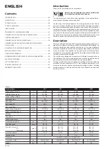
Introduction
Thank you for purchasing one for our products.
Before using the equipment you should carefully read
the instructions included in this manual.
It is also necessary to read all the safety regulations in the enclosed docu
-
ment „Safety instructions and maintenance“.
In order to get the best performance from the system and ensure that its
parts last as long as possible, you must strictly follow the usage instructions
and the maintenance regulations included in this manual. In the interest of
customers, you are recommended to have maintenance and, where nece
-
ssary, repairs carried out by the workshops of our service organisation, since
they have suitable equipment and specially trained personnel available. All
our machinery and systems are subject to continual development. We must
therefore reserve the right to modify their construction and properties.
Description
Machines 305, 405, 3500 and 4100 are professsional welding machines de
-
signed for MIG (Metal Inert Gas) and MAG (Metal Active Gas) welding. It is
sources of welding current with flat characteristics. It concerns welding in
protection atmosphere of active and intact gases when added material is in
a form of „infinite“ wire supplied into the weld by the wire feeding. These
methods are very productive, especially for the welds of construction steel,
low steel, aluminium and its alloys.
The machines are designed as movable sets, differing from each other in
their efficiency. The source of welding current, wire supply and feed are in
one compact metal case with two fixed and two turning wheels.
Welding machines have been designed for welding of thin and thickness
materials for wires used from 0.6 to 1.2 mm. Standard equipment of ma
-
chines can be found in chapter „Equipment of welding machines“. Welding
machines confirm to all European Union and Czech Republic standards and
directives in force.
Contents
ENGLISH
INTRODUCTION ...................................................................................... 20
DESCRIPTION .......................................................................................... 20
TECHNICAL DATA ................................................................................... 20
TYPES OF MACHINES .............................................................................
21
INSTALLATION ........................................................................................
21
EQUIPMENT OF WELDING MACHINES ................................................
21
CONNECTION TO THE ELECTRICAL POWER SUPPLY ...........................
21
CONTROL APPARATUS ...........................................................................
22
CONNECTION OF THE WELDING TORCH ............................................. 23
CONNECTION OF THE WELDING WIRE AND ADJUSTMENT
OF GAS FLOW ......................................................................................... 23
ADJUSTMENT OF WELDING PARAMETERS .......................................... 24
WELDING WORK CYCLES ....................................................................... 28
RATING PLATE SYMBOLS ....................................................................... 49
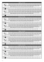
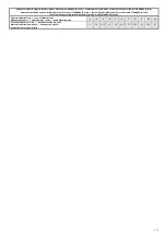
RECOMMENDED ADJUSTMENT OF WELDING PARAMETERS ............ 50
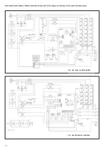
ELECTRICAL DIAGRAM .......................................................................... 54
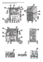
LIST OF SPARE PARTS ............................................................................. 55
TROUBLE SHOOTING LIST ..................................................................... 61
WARRANTY CERTIFICATE ...................................................................... 66
Table 1
Technical data
305
405
3500
4100
Mains voltage 50/60 Hz
[ V ]
3 x 400
3 x 400
3 x 400
3 x 400
Welding current range
[ A ]
30 - 280
30 - 350
30 - 280
50 - 350
Output voltage settings
[ V ]
17 - 38
18 - 40
19.2 - 41.9
22 - 51
Regulation steps
-
20
40
20
40
Duty cycle
[ A ]
280 (30 %)
350 (30 %)
280 (40 %)
350 (35 %)
Duty cycle 60 %
[ A ]
260
300
270
280
Duty cycle 100 %
[ A ]
220
260
235
240
Mains current/input 60 %
[ A/kVA ]
12.3 / 8.6
15.3 / 10.6
14.8 / 10.6
17.3 / 12.8
Mains protection-slow, D
[ A ]
25
25
25
25
Winding
-
Cu
Cu
Cu / Al
Cu / Al
Wire feeder
-
2-roll
4-roll
4-roll
4-roll
Digital voltammeter
-
Yes
Yes
Yes
Yes
Standardly equiped roll
[ mm ]
1.0 - 1.2
1.0 - 1.2
1.0 - 1.2
1.0 - 1.2
Wire feed speed
[ m/min ]
0.5 - 20
0.5 - 20
0.5 - 20
0.5 - 20
Diameter of wire - Fe
- Al
- Tube wire
[ mm ]
0.6 - 1.2
0.8 - 1.2
0.8 - 1.2
0.6 - 1.2
1.0 - 1.2
0.8 - 1.2
0.6 - 1.2
0.8 - 1.2
0.8 - 1.2
0.6 - 1.2
1.0 - 1.2
0.8 - 1.2
Protection degree
-
IP 21S
IP 21S
IP 21S
IP 21S
Insulation class
-
F
F
F, H
F, H
Standards
-
EN 60974-1, EN 60974-5, EN 60974-10
Dimensions LxWxH
[ mm ]
806x490x822
806x490x822
902x510x890
902x510x890
Weight
[ kg ]
93
101
88
93
EN
Summary of Contents for 305
Page 22: ... 67 ...


