


ANITA ©
MP01400EN_160801
29
-3
-5
-3
-5
-3
-5
-7
-1
-1
Stitch lenght [H]
Stichlänge [H]
2 mm
3 mm
2 mm
3 mm
2 mm
Needle height [H]
Nadelhöhe [H]
2,4 mm
2.0 mm
-3
-5
-3
-5
-7
Stitch lenght [H]
Stichlänge [H]
3 mm
Needle height [H]
Nadelhöhe [H]
2,4 mm
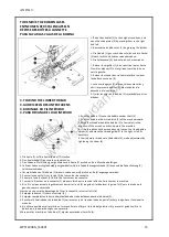
Needle bar height
1. Set the feed adjustment dial to the „0“ position.
2. When the needle bar (8) is in its lowest position, the needle position reference line (a) of the needle bar must be aligned
with the bottom edge of the needle bar support (9). Loosen the set screw (10), and align the needle position reference
line (a) of the needle bar with the bottom edge of the needle bar support (9).
Needle bar lift stroke
1. Turn the feed-adjustment dial to 2 or 3.
2. When the needle bar (8) is H mm (2.4 mm or 2.00 mm) above its lowest position, needle position reference line „b“ of
the needle bar is aligned with the bottom edge of the needle bar. At this time, the rotary hook point must e aligned with
the needle center. Loosen the three set screws (7), and align the rotary hook point with the needle center.
3. When the rotary hook point is aligned with the needle center, confirm that the space between the top of the needle eye
and rotary hook point is 1 ~ 1.5 mm.
Remove the set screw (11) turn the needle clamp screw (12), and adjust so that the space between the rotary hook point
and the top of the needle eye is 1 ~ 1.5 mm.
Nadelhöhe
1. Die Transporteinstellscheibe auf „0“ stellen.
2. Wenn die Nadelstange (8) H mm (2,4 mm oder 2,0 mm) über der untersten Position steht, muβ die Bezugslinie „b“ mit
der Unterkante der Nadelstangebuchse ausgerichtet sein. Der Greifer muβ azf due Badeknutte azsgerucgtet sein.
Der Greifer kann auf die Nadelmitte eingstellt werden, wenn die drei Schrauben (7) gelöst werden.
3. Wenn der Greifer auf die Nadelmitte ausgerichtet ist, kontrollieren, ob der Abstand zwischen der oberen Seite
des Nadelöhrs und dem Greifer 1 ~ 1,5 mm beträft.
Der Abstand zwischen der oberen Seite des Nadelöhrs und dem Greifer kann eingestellt werden, wenn die Schraube (11)
entfernt und die Einstellschraube (12) an Nadelhalter gedreht wird.
www.garudan.cz
Summary of Contents for GF-207-143
Page 44: ...ANITA MP01400CZ_160801 4 1 MACHINE BODY w w w g a r u d a n c z ...
Page 46: ...ANITA MP01400CZ_160801 6 2 UPPER SHAFT MECHANISM w w w g a r u d a n c z ...
Page 48: ...ANITA MP01400CZ_160801 8 3 NEEDLE BAR ROCKING MECHANISM w w w g a r u d a n c z ...
Page 50: ...ANITA MP01400CZ_160801 10 4 PRESSER FOOT MECHANISM w w w g a r u d a n c z ...
Page 52: ...ANITA MP01400CZ_160801 12 5 FEED MECHANISM w w w g a r u d a n c z ...
Page 54: ...ANITA MP01400CZ_160801 14 6 FEED SHAFT MECHANISM w w w g a r u d a n c z ...
Page 58: ...ANITA MP01400CZ_160801 18 8 LOWER SHAFT MECHANISM w w w g a r u d a n c z ...
Page 62: ...ANITA MP01400CZ_160801 22 10 LUBRICATION 1 3 w w w g a r u d a n c z ...
Page 64: ...ANITA MP01400CZ_160801 24 10 LUBRICATION 2 3 w w w g a r u d a n c z ...
Page 66: ...ANITA MP01400CZ_160801 26 10 LUBRICATION 3 3 w w w g a r u d a n c z ...
Page 68: ...ANITA MP01400CZ_160801 28 11 THREADING MECHANISM w w w g a r u d a n c z ...
Page 82: ...ANITA MP01400CZ_160801 42 17 GAUGE PARTS w w w g a r u d a n c z ...
Page 84: ...ANITA MP01400CZ_160801 44 18 ACCESSORIES 1 2 w w w g a r u d a n c z ...
Page 86: ...ANITA MP01400CZ_160801 46 18 ACCESSORIES 2 2 w w w g a r u d a n c z ...
Page 88: ...ANITA MP01400CZ_160801 48 19 GAUGE PARTS LIST w w w g a r u d a n c z ...
Page 89: ...ANITA MP01400CZ_160801 49 w w w g a r u d a n c z ...