GARO LS4 Wallmounted Operational Instructions Download Page 10

9

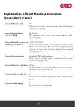
Explanation of DLM Master parameters 

(With, or without, secondary meter)

Dynamic Load 

Management

DLM Network ID

DLM Algorithm 

EVSE Sub‐Distribution 

Limit (L1/L2/L3)[A] 

Operator EVSE Sub‐

Distribution Limit 

(L1/L2/L3)[A]

External Input 1 Config 

External Input 2 Config


DLM Master with internal DLM‐Slave

Define the role of the controller in the DLM cluster as the 
Master with its own charging equipment connected to it.

0

Shows which ID (could be any between 0‐255). The DLM 
Slaves will use this ID to find their specific Master.

FIFO

F

irst 

I

F

irst 

O

ut – The only available Algorithm in 4.2X‐4.3X. 

More on the way.

32   32   32

Defines the mutual main fuse for all the controllers in the DLM 
cluster (In the specific case 32A on all phases).

32   32   32

Same as the one above, but this is configurable downwards 
from the backend. (Can never be higher than the EVSE Sub-
‐Distribution Limit (L1/L2/L3)[A])

DISABLE

(Not yet implemented on the LS4)

DISABLE

(Not yet implemented on the LS4)

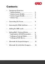
Summary of Contents for LS4 Wallmounted

Page 1: ...LS4 GLB Operational Instructions...

Page 2: ...or Top Connecting the Power Accessing the Web Interface Adding the RFID cards Setting DLM External Meter Explanation of DLM Parameters Setting up External Meter Setting up DLM Slaves Schematic for loo...

Page 3: ...Interior Bottom Interior Lower Middle 2...

Page 4: ...3 Interior Upper Middle Interior Top...

Page 5: ...4 Connecting the Laptop computer...

Page 6: ...ss field type in 192 168 123 123 operator and press ENTER to navi gate to the web interface startup page where you get to choose which controller master or slave you want to connect to Access to the c...

Page 7: ...ters from the Settings view and also more advanced settings when it comes to connectivity communication monitoring authentication and behavior during operation Operator demands operator or manufacture...

Page 8: ...croll down to Free Charging approx half way Select if in doubt allow charging select ON Select SAVE on Laptop Plug in CAR or TEST Equipment to master socket LHS Activate CP Button Place new RFID card...

Page 9: ...8 Setup of DLM with external Secondary Meter...

Page 10: ...charging equipment connected to it 0 Shows which ID could be any between 0 255 The DLM Slaves will use this ID to find their specific Master FIFO First In First Out The only available Algorithm in 4...

Page 11: ...use of the entire premise build ing area grid 9999 9999 9999 In case of a disconnection from the external meter the DLM Master will assume this is the load that is being drawn from the meter A high va...

Page 12: ...Meter configuration Second Phase rotation of the ChargePoint Model of the external meter This meter should be addressed 2 and be connected to the DLM masters meter bus RST L1 L2 L3 Standard Reference...

Page 13: ...ific Master 6 The minimum current the chargepoint need to start charging a car 6 The maximum current the DLM Slave will be allowed to use if disconnected from the DLM Master If disconnected the DLM Ma...

Page 14: ...13...

Page 15: ...14...

Reviews: