background image

GTX 330 Installation Manual

Page 4-5

190-00207-02

Rev. 1

4.6

Serial Data Electrical Characteristics

Pin Name

Connector

Pin

I/O

RS 232 OUT 1

P3301

23

Out

RS 232 IN 1

P3301

22

In

RS 232 OUT 2

P3301

23

Out

RS 232 IN 2

P3301

24

In

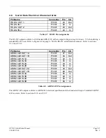
Table 4-7.  RS 232 Pin Assignments

The RS-232 outputs conform to EIA Standard RS-232C with an output voltage swing of at least ± 5 V when driving a
standard RS-232 load.  Refer to Figure 4-2 on page 4-7 for the RS-232 serial data interconnect.  Refer to sections
5.2.9. and 5.2.16.

Pin Name

Connector

Pin

I/O

ARINC 429 OUT 1A

P3301

37

Out

ARINC 429 OUT 1B

P3301

34

Out

ARINC 429 IN 1A

P3301

32

In

ARINC 429 IN 1B

P3301

35

In

ARINC 429 IN 2A

P3301

33

In

ARINC 429 IN 2B

P3301

36

In

ARINC 429 OUT 2A

P3301

30

Out

ARINC 429 OUT 2B

P3301

28

Out

ARINC 429 IN 3A

P3301

26

In

ARINC 429 IN 3B

P3301

29

In

ARINC 429 IN 4A

P3301

48

In

ARINC 429 IN 4B

P3301

49

In

Table 4-8.  ARINC 429 Pin Assignments

The ARINC 429 outputs conform to ARINC 429 electrical specifications when loaded with up to 5 standard ARINC
429 receivers.  Refer to sections 5.2.8. and 5.2.17.

Summary of Contents for GTX 330

Page 1: ...GARMIN International Inc 1200 E 151st Street Olathe KS 66062 USA 190 00207 02 Revision 1 March 2002 GTXTM 330 GTXTM 330D TRANSPONDER INSTALLATION MANUAL...

Page 2: ...ect to change without notice GARMIN reserves the right to change or improve its products and to make changes in the content without obligation to notify any person or organization of such changes or i...

Page 3: ...GTX 330 Installation Manual Page i 190 00207 02 Rev 1 TABLE OF CONTENTS To be supplied...

Page 4: ...Page ii GTX 330 Installation Manual Rev 1 190 00207 02 This page intentionally left blank...

Page 5: ...r TCAS interrogations at 1030 MHz and transmitting a coded response of pulses to ground based radar on a frequency of 1090 MHz The GTX 330 is equipped with IDENT capability that activates the Special...

Page 6: ...121 010 JTSO 2C112a TSO JTSO GTX 330D TSO C112 CL2A4 121 011 JTSO 2C112a TSO ENV CAT Refer to appendix A Applicable Documents RTCA DO 160D DO 181C Temperature Range 45 C to 55 C Continuous Operation P...

Page 7: ...30 Unit Weight 3 4 lbs 1 5 kg GTX 330 Rack Weight Installed with rack and connectors 4 2 lbs 1 9 kg 1 4 3 GTX 330 Configurations Available GARMIN P N GTX 330 Description 010 00230 00 Black Front Panel...

Page 8: ...on or within a specific type or class of aircraft to determine that the aircraft installation standards are within the TSO standards For GTX 330 TSO compliance see Appendix A For antenna TSO complian...

Page 9: ...RANTY GIVES YOU SPECIFIC LEGAL RIGHTS WHICH MAY VARY FROM STATE TO STATE IN NO EVENT SHALL GARMIN BE LIABLE FOR ANY INCIDENTAL SPECIAL INDIRECT OR CONSEQUENTIAL DAMAGES WHETHER RESULTING FROM THE USE...

Page 10: ...Page 1 6 GTX 330 Installation Manual Rev 1 190 00207 02 This page intentionally left blank...

Page 11: ...unit to GARMIN until the carrier has authorized the claim Retain the original shipping containers for storage If the original containers are not available a separate cardboard container should be pre...

Page 12: ...ressure vessel by connector holes and or mounting arrangements For needed engineering support pertaining to the design and approval of such pressurized aircraft antenna installations it is recommended...

Page 13: ...es of the recommended antenna cable vendors and the type of cable to be used for specific lengths of cable Any cable meeting specifications is acceptable for the installation The maximum coaxial cable...

Page 14: ...ional cooling is provided Allow adequate space for installation of cables and connectors The installer will supply and fabricate all of the cables All wiring must be in accordance with FAA AC 43 13 2A...

Page 15: ...associated hardware are supplied in the connector kit P N 011 00583 00 See figures 4 1 and 4 2 for interconnect wiring diagrams CAUTION Check wiring connections for errors before inserting the GTX 330...

Page 16: ...POST INSTALLATION CHECKOUT CAUTION Be sure to check all aircraft control movements before flight is attempted to insure that the wiring harness does not touch any moving part Verify proper operation o...

Page 17: ...GTX 330 Installation Manual Page 3 5 Page 3 6 blank 190 00207 02 Rev 1 Figure 3 1 GTX 330 OUTLINE DRAWING...

Page 18: ...GTX 330 Installation Manual Page 3 7 Page 3 8 blank 190 00207 02 Rev 1 Figure 3 2 GTX 330 CONNECTOR RACK ASSEMBLY DRAWING...

Page 19: ...GTX 330 Installation Manual Page 3 9 Page 3 10 blank 190 00207 02 Rev 1 Figure 3 3 GTX 330 RECOMMENDED PANEL CUTOUT DIMENSIONS...

Page 20: ...DE A4 In 6 ALTITUDE C4 In 7 ALTITUDE B1 In 8 ALTITUDE C1 In 9 ALTITUDE B2 In 10 ALTITUDE B4 In 11 ALTITUDE D4 In 12 EXTERNAL IDENT SELECT In 13 EXTERNAL STANDBY SELECT In 14 28 V LIGHTING BUS HI In 15...

Page 21: ...2 AIRCRAFT POWER In 43 AIRCRAFT GROUND 44 TEMPERATURE PROBE 2 IN In 45 14 V 5 V LIGHTING BUS HI In 46 TIS CONNECT SELECT In 47 RESERVED 48 ARINC 429 IN 4 A In 49 ARINC 429 IN 4 B In 50 ALTITUDE COMMON...

Page 22: ...330 unit can be configured to track a 28 VDC 14 VDC 5 VDC or 5 VAC lighting bus using these inputs The GTX 330 can also automatically adjust for ambient lighting conditions based on the photocell Ref...

Page 23: ...ALTITUDE C4 P3301 6 In ALTITUDE COMMON P3301 50 Table 4 5 Encoded Altitude Pin Assignments 4 4 1 Altimeter Calibration and Checkout Refer to section 5 2 13 for the gray code altitude checkout 4 4 2 A...

Page 24: ...RS 232 serial data interconnect Refer to sections 5 2 9 and 5 2 16 Pin Name Connector Pin I O ARINC 429 OUT 1A P3301 37 Out ARINC 429 OUT 1B P3301 34 Out ARINC 429 IN 1A P3301 32 In ARINC 429 IN 1B P3...

Page 25: ...Page 4 6 GTX 330 Installation Manual Rev 1 190 00207 02 This page intentionally left blank...

Page 26: ...GTX 330 Installation Manual Page 4 5 Page 4 6 blank 190 00207 02 Rev 1 Figure 4 1 GTX 330 INTERCONNECT WIRING DIAGRAM...

Page 27: ...GTX 330 Installation Manual Page 4 7 Page 4 8 blank 190 00207 02 Rev 1 Figure 4 2 DUAL TXP INTERCONNECT WIRING DIAGRAM ENCODING ALTITUDE CONNECTIONS...

Page 28: ...330 Pressing the STBY ON or ALT key powers on the transponder displaying the last active identification code STBY Selects the standby mode When in standby mode the transponder will not reply to any i...

Page 29: ...in Configuration Mode CLR Resets the Count Up Count Down and Flight timers Cancels the previous keypress during code selection and Count Down entry Used in Configuration Mode 8 Reduces Contrast and D...

Page 30: ...plied to the GTX 330 in feet hundreds of feet i e flight level or meters depending on configuration FLIGHT TIME Displays the Flight Time controlled by the START STOP key or by one of three airborne so...

Page 31: ...nges Changes made through the configuration pages are stored in EEPROM memory To exit the configuration pages turn the power off and then on again without holding the FUNC key The configuration page s...

Page 32: ...ume page I O CONFIG Jumps to ARINC 429 INPUT 1 page ACFT CONFIG Jumps to configuration Operation Configuration 1 page 5 2 2 AUDIO MODE Pages AUDIO MODE Selection Description VOICE MALE FEMALE Sets the...

Page 33: ...n be entered when the manual mode is selected AUTO Automatic DEFAULT Display backlighting is automatically controlled based on the parameters entered on this configuration page When AUTO is selected t...

Page 34: ...50 at the factory OFFSET Adjusts the lighting level up or down for any given input level This field has a range of 0 zero to 99 and is set to 50 at the factory This may also be used to match lighting...

Page 35: ...the key lighting brightness to changes in the input level The higher the number the brighter the key lighting will be for a given increase in the input level This field has a range of 0 zero to 99 an...

Page 36: ...ystick waypoint and speed information ARINC 429 OUTPUT The ARINC 429 OUTPUT Pages configure the ARINC 429 output ports Each port can be configured independently for the desired function s Selection De...

Page 37: ...FR Transponder Code This field is the four digit code that will be selected when the user presses the GTX 330 VFR key In the United States 1200 is the VFR code for any altitude It is set to 1200 at th...

Page 38: ...s master switch The unit will perform a self test routine and display a Jump to Diagnostics page 3 Press the FUNC key repeatedly to toggle through the pages until you come to the address entry page a...

Page 39: ...e AIRCRAFT AIRSPEED Message to a speed of Less Than or equal to 75 Knots Less Than or equal to 150 Knots Less Than or equal to 300 Knots More Than 300 Knots or Unknown airspeed Defaults to Less Than o...

Page 40: ...e of the EXTERNAL STANDBY discrete input The box is filled when EXTERNAL STANDBY is grounded SQUAT This field displays the state of the SQUAT SWITCH input The box is filled when the SQUAT SWITCH input...

Page 41: ...Page 5 14 GTX 330 Installation Manual Rev 1 190 00207 02 This page intentionally left blank...

Page 42: ...case they should be marked N A Not Applicable INSTRUCTIONS FOR CONTINUED AIRWORTHINESS GARMIN GTX 330 1 Introduction Aircraft that has been altered Registration N number Make Model and Serial Number...

Page 43: ...N A 13 This Section is for Commuter Category Aircraft Only A Electrical loads Refer to section 1 3 of this manual B Methods of balancing flight controls N A C Identification of primary and secondary...

Page 44: ...t the ICA is made part of the applicable section 91 409 inspection program for their aircraft This is accomplished when a maintenance entry is made in the aircraft s maintenance record in accordance w...

Page 45: ...s A2 B2 F1 Low Temperature 4 5 1 45 degrees C High Temperature 4 5 2 4 5 3 70 degrees C In Flight Loss of Cooling 4 5 4 Cooling air not required but highly recommended Altitude 4 6 1 55 000 Feet Decom...

Page 46: ...t tested to Category BZ Voltage Spike 17 0 Equipment tested to Category A Audio Frequency Conducted Susceptibility 18 0 Equipment tested to Category Z Induced Signal Susceptibility 19 0 Equipment test...

Page 47: ...on Manual Page B1 190 00207 02 Rev 1 APPENDIX B STC PERMISSION Consistent with N8110 69 or Order 8110 4 Aviation Authority approved installers are hereby granted permission to use STC xxxxxxxxx data t...

Page 48: ...Page B2 GTX 330 Installation Manual Rev 1 190 00207 02 To be supplied...

Reviews: