Step 3: Connect to the Radio
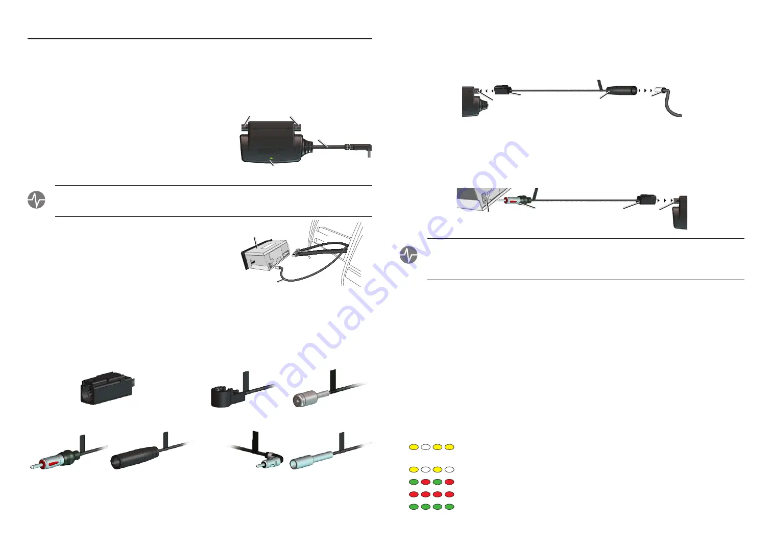
The GTM 10 connects in series between the antenna and radio, using the adapter cables chosen in Step 2.
1. Connect the antenna plug to the appropriate female (receptacle) adapter cable. Connect the Fakra plug to
the
In
connector on the GTM 10. The Fakra plug locks firmly in place.
Fakra
connector
Female
adapter
Antenna
connector
GTM 10
In
If the antenna cable has a Fakra connector, no adapter cable is needed between the antenna cable and the
GTM 10
In
connector. Connect the Fakra antenna cable directly into the
In
connector of the GTM 10. Then
use the supplied dual-ended Fakra cable to connect the GTM 10 to the radio, as described below.
2. Connect the Fakra connector of the adapter cable to the
Out
connector of the GTM 10. Connect the male
(plug) adapter cable into the radio receptacle, as shown below.
Fakra
connector
Male
adapter
Radio
receptacle
GTM 10
Out
teSt: Turn on the vehicle’s radio. If sound from an FM radio station can be heard, the GTM 10 and its
cables are properly connected. If no sound is heard, the GTM 10 is not connected correctly. Check that all
cables are locked into place and free of obstructions. If the connections are secure, make sure the chosen
adapter cables are correct for the vehicle.
Step 4: Connect to the GPS Device
Refer to question 1 on the Owner Questionnaire for the owner’s instructions on how to route the cable up to
the GPS. Route the mini-USB cable from behind the radio on the passenger’s side of the vehicle up to the
GPS device. If possible, thread the cable through an existing opening in the glove box or trim panel. Thread
enough cable through the opening to reach the GPS device.
Do not cut the mini-USB cable.
If the mini-USB cable is not long enough to reach the GPS device, a 2-meter extension cable is available for
purchase from a Garmin dealer or from the Garmin Web site at
http://www.garmin.com/products/gtm10
Step 5: Test the GTM 10
Test the GTM 10 for proper installation and service reception. Connect the mini-USB connector to the
Garmin GPS device, if you have access to the GPS.
• Observe the LED:
Turn on the GPS device. Service reception is indicated by the solid green light, which
may take up to five minutes to appear for initial data acquisition.
Yellow dot-dash flashes: waiting for initial country code, automatically supplied by the
Garmin GPS device.
Yellow fast flashes: searching table for active entry
Red/Green flashes: scanning for new TMC FM stations
Red solid light: momentary sync loss
Green solid light: normal TMC traffic data flow. The GTM 10 must be in an area of service
and be receiving adequate signals to display a solid green light.
For the Installer
The GTM 10 FM TMC Traffic Receiver installs between a vehicle’s radio and its antenna cable. Carefully
read this
Installation Sheet
and follow the instructions to install the GTM 10 in the vehicle.
GTM 10 Overview
The GTM 10 has two cable connectors that allow it to be installed in series between the antenna and radio.
Do
not open the GTM 10 or loosen the case screws.
In
: In from antenna. Connect the antenna adapter here.
Out
: Out to radio. Connect the radio adapter cable here.
LED
: displays the signal status.
Mini-USB cable
: 1.5-meter built-in cable to connect to a Garmin
GPS device.
Step 1: Prepare the Radio
teSt: Before installation, test the vehicle’s radio to ensure that the antenna is functioning properly and the
radio can receive all normal FM signals. If the antenna functions improperly, the GTM 10 may not work
properly. Consult the owner about continuing with installation.
Remove the trim panel and other parts of the dashboard to
access the vehicle’s radio antenna cable. You may need to
remove the radio as well. Detach the antenna cable.
Step 2: Choose the Appropriate Cables
The GTM 10 ships with several adapter cables. Each cable
contains at least one Fakra connector for connecting to the
GTM 10 In/Out receptacles. Except for the dual-ended Fakra cable, the cables are grouped in pairs: for each
cable with a male end (plug) there is a matching cable with a female end (receptacle).
European and UK packages include one cable that has two Fakra connectors, one pair of ISO cables, and
one pair of Motorola cables. The US package includes one cable that has two Fakra connectors, one pair of
Motorola cables, and one pair of GM cables.
Motorola Male (Plug)
Motorola Female (Receptacle)
GM Male (Plug)
GM Female (Receptacle)
Fakra Connector
ISO Male (Plug)
ISO Female (Receptacle)
To select the proper pair of cables to use, match the adapter cable male end (plug) to the vehicle’s radio
antenna cable plug. Use that pair of cables for the installation. If the antenna has a Fakra connector, use the
dual-ended Fakra cable between the GTM 10 and the radio.
Radio
Antenna Cable
In
Mini-USB cable
(cord is not to scale)
Out
LED


