Garmin GPSMAP 8000 Series Owner'S Manual Download Page 15

the bottom of the keel instead of from the transducer location. 

Enter a positive number to offset for a keel. You can enter a 

negative number to compensate for a large vessel that may 

draw several feet of water.

1

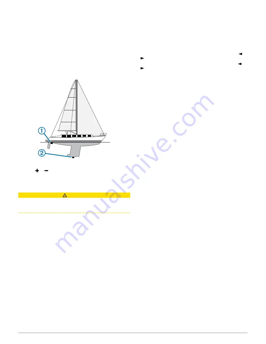
Complete an action, based on the location of the transducer:
• If the transducer is installed at the water line 

À

, measure

the distance from the transducer location to the keel of the

boat. Enter this value in steps 3 and 4 as a positive

number.

• If the transducer is installed at the bottom of the keel 

Á

,

measure the distance from the transducer to the water

line. Enter this value in steps 3 and 4 as a negative

number.

2

Select 

Settings

 > 

My Vessel

 > 

Keel Offset

.

3

Select   or   based on the location of the transducer.

4

Enter the distance measured in step 1.

Sailboat Autopilot Operation

 CAUTION

When engaged, the autopilot controls only the rudder. You and 

your crew remain responsible for the sails while the autopilot is 

engaged.

In addition to heading hold, you can use the autopilot to maintain 

a wind hold. You can also use the autopilot to control the rudder 

while tacking and gybing.

Wind Hold

You can set the autopilot to maintain a specific bearing relative 

to the current wind angle. Your device must be connected to a 

NMEA 2000 or NMEA

®

 0183 compatible wind sensor to perform 

a wind hold or a wind-based tack or gybe.

Setting the Wind Hold Type

Before you can enable the wind hold type, you must connect a 

NMEA 2000 or NMEA 0183 wind sensor to the autopilot.
For advanced autopilot configuration, see the installation 

instructions included with your autopilot.

1

From the autopilot screen, select 

Menu

 > 

Autopilot Setup

 > 

Wind Hold Type

.

2

Select 

Apparent

 or 

True

.

Engaging Wind Hold

Before you can enable the wind hold type, you must connect a 

NMEA 2000 or NMEA 0183 wind sensor to the autopilot.

When the autopilot is in standby mode, select 

Wind Hold

.

Engaging Wind Hold from Heading Hold

Before you can enable the wind hold type, you must connect a 

NMEA 2000 or NMEA 0183 wind sensor to the autopilot.

With heading hold engaged, select 

Menu

 > 

Wind Hold

.

Adjusting the Wind Hold Angle with the Autopilot

You can adjust the wind hold angle on the autopilot when wind 

hold is engaged.
• To adjust the wind hold angle in increments of 1°, select   or

.

• To adjust the wind hold angle in increments of 10°, hold   or

.

Tack and Gybe

You can set the autopilot to perform a tack or gybe while 

heading hold or wind hold is engaged.

Tacking and Gybing from Heading Hold

1


Engage heading hold (Engaging the Autopilot).

2


Select 

Menu

 > 

Tack/Gybe

.

3


Select a direction.
The autopilot steers your boat through a tack or gybe.

Tacking and Gybing from Wind Hold

Before you can engage wind hold, you must have a wind 
sensor installed.

1


Engage wind hold (Engaging Wind Hold).

2


Select 

Menu

 > 

Tack/Gybe

.

3


Select 

Tack

 or 

Gybe

.

The autopilot steers your boat through a tack or gybe, and 

information about the progress of the tack or gybe appears 

on the screen.

Setting a Tack and Gybe Delay

The tack and gybe delay allows you to delay steering a tack and 

gybe after you initiate the maneuver.

1

From the autopilot screen, select 

Menu

 > 

Autopilot Setup

 > 

Sailing Setup

 > 

Tack Delay

.

2

Select the length of the delay.

3

If necessary, select 

Done

.

Enabling the Gybe Inhibitor

NOTE: 

The gybe inhibitor does not prevent you from manually 

performing a gybe using the helm or step steering.
The gybe inhibitor prevents the autopilot from performing a 

gybe.

1

From the autopilot screen, select 

Menu

 > 

Autopilot Setup

 > 

Sailing Setup

 > 

Gybe Inhibitor

.

2

Select 

Enabled

.

Sonar

When properly connected to an optional Garmin sounder 

module and a transducer, your compatible chartplotter can be 

used as a fishfinder. Different sonar views can help you view the 

fish in the area.
The adjustments you can make to each sonar view vary 

depending on the view you are in and the chartplotter model, 

sounder module, and transducer you have connected.

Sonar Views

The sonar views available vary depending on the type of 

transducer and optional sounder module connected to the 

chartplotter. For example, you can view the Split Frequency 

view only if you have a dual-frequency transducer connected.
There are four basic styles of sonar views available: a full-

screen view, a split-screen view that combines two or more 

14

Sonar

Summary of Contents for GPSMAP 8000 Series

Page 1: ...GPSMAP 8000 Series Owner s Manual...

Page 2: ...nother compatible chartplotter or a computer 1 Open the door on the memory card reader 2 Insert the memory card with the label facing away from the door 3 Press the card in until it clicks 4 Close the...

Page 3: ...bination Page You can customize the layout and data shown in the combination pages and SmartMode layouts When you change the layout of a page in a display you are interacting with the change appears o...

Page 4: ...es a detailed view of the bottom contours and depth soundings on the chart This chart removes navigational data from the chart provides detailed bathymetric data and enhances bottom contours for depth...

Page 5: ...nta line NOTE When using Auto Guidance a gray segment within any part of the magenta line indicates that Auto Guidance cannot calculate part of the Auto Guidance line This is due to the settings for m...

Page 6: ...nsponder and that are actively transmitting AIS information The information reported for each vessel includes the Maritime Mobile Service Identity MMSI location GPS speed GPS heading time that has ela...

Page 7: ...device or radar The safe zone collision alarm is used only with AIS and MARPA MARPA functionality works with radar The safe zone is used for collision avoidance and can be customized 1 Select Settings...

Page 8: ...hart Views From a chart or a 3D chart view select Menu Waypoints and Tracks Tracks Shows tracks on the chart or 3D chart view Waypoints Shows the list of waypoints Viewing a List of all Waypoints Crea...

Page 9: ...tination but allows you to add turns into the route to avoid land and other obstacles Auto Guidance Creates a path to a destination using Auto Guidance This option is available only when using a compa...

Page 10: ...d a corrected course may pass over land or shallow water Use visual sightings and steer to avoid land shallow water and other dangerous objects NOTE Auto Guidance is available with premium charts in s...

Page 11: ...low the magenta line along each leg in the route steering to avoid land shallow water and other obstacles 7 If you are off course follow the purple line corrected course to go to your destination or s...

Page 12: ...tplotter uses when calculating an Auto Guidance line NOTE The minimum safe depth for the premium charts is 3 feet If you enter a Safe Depth value of less than 3 feet the charts only use depths of 3 fe...

Page 13: ...t an option To navigate the track from the starting point used when the track was created select Forward To navigate the track from the destination point used when the track was created select Backwar...

Page 14: ...t line when the timer expires By default the start line guidance window and the race timer window appear in the Sail Racing combination screen Setting the Starting Line The start line guidance window...

Page 15: ...hold engaged select Menu Wind Hold Adjusting the Wind Hold Angle with the Autopilot You can adjust the wind hold angle on the autopilot when wind hold is engaged To adjust the wind hold angle in incre...

Page 16: ...to the sides of the boat You can use this as a search tool to find structures and fish Left side of the boat Right side of the boat The transducer on your vessel Trees Old tires Logs Distance from the...

Page 17: ...Mode layout with sonar select the window to change 2 Select Menu Change Sonar 3 Select a sonar view Creating a Waypoint on the Sonar Screen 1 From a sonar view select a location 2 Select New Wpt 3 If...

Page 18: ...atic option Adjusting the Color Intensity You can adjust the intensity of colors and highlight areas of interest on the sonar screen by adjusting the color gain for traditional transducers or the cont...

Page 19: ...For more information on frequencies see Sonar Frequencies Creating a Frequency Preset NOTE Not available with all transducers You can create a preset to save a specific sonar frequency which allows y...

Page 20: ...he movement of the target Grid Overlay Shows a grid of range lines Noise Reject Reduces the interference and the amount of clutter shown on the sonar screen Scroll History Shows the sonar history in a...

Page 21: ...w select Menu Sonar Setup Installation Transmit Rate Sets the length of time between sonar pings Increasing the transmit rate increases the scroll speed but it may also increase self interference Redu...

Page 22: ...ed in the radar installation instructions 2 Turn on the chartplotter The radar warms up and a countdown alerts you when the radar is ready 3 Select Radar 4 Select a radar mode A countdown message appe...

Page 23: ...h it indicates that the radar could not lock onto the target Closest point of approach and time to closest point of approach to a dangerous target Assigning a MARPA Tag to an Object Before you can use...

Page 24: ...overlay displays data based on the most recently used radar mode Select Charts Radar Overlay The radar picture appears in orange and overlays the navigation chart Setting a Custom Park Position If you...

Page 25: ...sting Sea Clutter on the Radar Screen Manually You can adjust the appearance of clutter caused by choppy sea conditions The sea clutter setting affects the appearance of nearby clutter and targets mor...

Page 26: ...Radar Setup Source Select Settings Communications Preferred Sources Radar 2 Select the radar source Autopilot WARNING You can use the autopilot feature only at a station installed next to a helm thro...

Page 27: ...1 From the autopilot screen select Menu Pattern Steering Williamson Turn 2 Select Engage Port or Engage Starboard Following an Orbit Pattern You can use the orbit pattern to steer the boat in a contin...

Page 28: ...plotter screen prompting you to activate navigation to the man overboard location disappears Man Overboard and SOS Distress Calls Initiated from the Chartplotter When your chartplotter is connected to...

Page 29: ...screen select Menu Gauge Setup Set Gauge Limits 2 Select a gauge 3 Select Mode Custom 4 Select an option To set the minimum value of the standard operating range select Rated Min To set the maximum va...

Page 30: ...les To set the maximum and minimum values that appear when the downwind close hauled wind gauge appears select Change Downwind Scale and set the angles To view true or apparent wind select Wind and se...

Page 31: ...connected You can play media from sources connected to the media player and sources connected to the NMEA 2000 network Your chartplotter and iPod can be connected using a FUSION Link capable stereo O...

Page 32: ...ting a SiriusXM Radio ID Before you can activate your SiriusXM subscription you must have the radio ID of your SiriusXM Connect Tuner You can locate the SiriusXM Radio ID on the back of the SiriusXM C...

Page 33: ...rce that provides the information changes Changing the Weather Chart 1 From a combination screen or SmartMode layout with a weather chart select Menu Weather Menu Change Weather 2 Select a weather cha...

Page 34: ...ditions chart using wind barbs that indicate the direction from which the wind is blowing A wind barb is a circle with a tail The line or flag attached to the tail of the wind barb indicates the wind...

Page 35: ...view surface wind and barometric pressure information select Sea Surface To view wind and wave information select Marine Bulletin Creating a Waypoint on a Weather Chart 1 From a weather chart select...

Page 36: ...he color scheme of the infrared image Change Scene Selects the infrared image mode such as day night MOB or docking Video Setup Opens more video options Video Settings Some cameras provide additional...

Page 37: ...evice to the Chartplotter You can connect up to five VIRB X XE action cameras to the chartplotter After you connect the VIRB X XE action camera with the chartplotter a new option is added to A V Gauge...

Page 38: ...or chart that specifies a different map datum Time Sets the time format time zone and daylight saving time Navigation Settings NOTE Some settings and options require additional charts or hardware Sel...

Page 39: ...ch NMEA 0183 Port Output Sentences See Configuring NMEA 0183 Output Sentences Position Precision Adjusts the number of digits to the right of the decimal point for transmission of NMEA output XTE Prec...

Page 40: ...the keel measure the distance from the transducer to the water line Enter this value in steps 3 and 4 as a negative number 2 Select Settings My Vessel Keel Offset 3 Select or based on the location of...

Page 41: ...Wi Fi Network Advanced Channel 2 Enter a new channel You do not need to change the wireless channel of devices connected to this network Changing the Wi Fi Host You can change which chartplotter is se...

Page 42: ...Select Copy Built In Map Backing Up Data to a Computer 1 Insert a memory card into the card slot 2 Select Info User Data Data Transfer Save to Card 3 Select a file name from the list or select Add Ne...

Reviews: