


GPSMAP 6000/7000 Series Installation Instructions
9
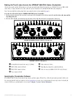
Creating a Basic NMEA 2000 Network
If your boat does not already have an existing NMEA 2000
network installed, you must create a basic NMEA 2000 network.
to create a basic NMEA 2000 network:
1. Connect the three included T-connectors together, side by
side.
2. Connect the terminators to the ends of the combined
T-connectors.
3. Wire the included NMEA 2000 power cable to a 12 Vdc power
source through a switch. Connect the power cable to the
ignition switch of the boat if possible.
4. Connect the NMEA 2000 power cable to the top of one of the
T-connectors.
5. Route and connect the included NMEA 2000 drop cables
from the GPS 17x and from the GPSMAP 6000/7000 series
chartplotter to the tops of the other T-connectors.
NotES:
• The diagram shows only the NMEA 2000 data connection
to the GPSMAP 6000/7000 series chartplotter. The
chartplotter must also be connected to power or it will not
function (
).
• One GPS antenna will provide position data for every
device on the NMEA 2000 network. Do not connect
multiple GPS antennas if you are using multiple
chartplotters.
Wiring a Garmin Marine Network
The optional Garmin Marine Network is a plug-and-play system that allows for high-speed data transfer between multiple Garmin chartplotters
and other network-compatible Garmin devices such as a Garmin sonar unit (GSD 22), or a Garmin radar (GMR™ 18 HD or GMR 1206 xHD).
The GPSMAP 6000/7000 series chartplotters have three network ports that can be used to connect other Garmin network-compatible
chartplotters and devices. If the network requires more ports, use a Garmin Marine Network port extender (GMS 10), or another GPSMAP
6000/7000. Data from each connected component is shared by all the connected Garmin chartplotters.
NoteS:
• NMEA 0183 devices must all be wired to one chartplotter on the network. The data is then shared over the network to other connected
chartplotters.
• Connect all chartplotters to the NMEA 2000 network as well as to the Garmin Marine Network. NMEA 2000 data is not shared over the
Garmin Marine Network.
• Connect network components, such as a Garmin GMR radar or GSD sounder to any chartplotter on the network or to an optional GMS 10
Network Port Expander. Data is shared between all chartplotters on the network.
• BlueChart
®
g2 Vision
®
cartography data is shared between any connected GPSMAP 6000/7000 series and GPSMAP 4000/5000 series
chartplotter.
• Video inputs from the Marine Video cables are only viewable on the connected chartplotter.
• You can connect a GPSMAP 6000/7000 chartplotter to a Marine Network with a GPSMAP 3000 series chartplotter:
◦ They will share GPS position information as well as information to and from standard NMEA 0183 devices.
◦ They will share information from connected network compatible Garmin devices such as a sonar unit (GSD 22) or a radar (GMR 18 HD
or GMR 1206 xHD).
◦ Garmin GPSMAP 3000 series chartplotters cannot share cartography data with the GPSMAP 6000/7000 series chartplotters.
• All network components must be connected to the power source of the boat according to their installation instructions. The following
diagrams show only the network connections, not power connections..
Creating a Basic NMEA 2000 Network
+
-
Drop cables
Male
terminator
T-connectors
Female
terminator
NMEA 2000
power cable
Ignition or
in-line switch
12 Vdc battery
Fuse
GPS 17x
antenna
GPSMAP 6000/7000
series chartplotter


