Garmin GPSMAP 6000 Series Installation Instructions Manual Download Page 11

GPSMAP 6000/7000 Series Installation Instructions 

 11

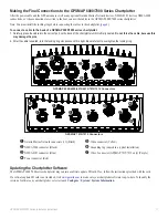
Connecting a GPSMAP 6000/7000 Series Chartplotter to an Existing Garmin Marine Network

xx

xxxxxxxxxxxxxxxxxxxxxxxxx

Garmin 

GPSMAP 6000/7000 

series chartplotter

GSD 22 sounder unit

To transducer

Garmin marine radar

Garmin  

GPSMAP 3000 series 

chartplotter

GMS 10 marine network port expander

GDL 30A 

XM weather receiver

NoteS:

•  Every device connected to the Garmin Marine Network must be connected to the power supply for the boat. These diagrams show the 

network connections; however, they 

do not show the power connections

. Wire each device according to the appropriate installation 

instructions.

•  These diagrams show the Garmin Marine Network connections; however, they 

do not show NMeA 2000 or NMeA 0183 connections

.

•  When connecting a GPSMAP 6000/7000 series chartplotter to an existing Garmin Marine Network, the GMS 10 can be used but is not 

necessary. The GPSMAP 6000/7000 series chartplotter has three network ports and acts as a port expander. Wire the GPS antenna and 

additional NMEA devices to either an existing chartplotter or the new GPSMAP 6000/7000 Series chartplotter. The existing chartplotter and 

the new GPSMAP 6000/7000 series chartplotter share NMEA 0183 data and Garmin Marine Network data.

Summary of Contents for GPSMAP 6000 Series

Page 1: ...us better support you by completing our online registration today Go to http my garmin com Keep the original sales receipt or a photocopy in a safe place For future reference write the serial numbers...

Page 2: ...mounting hardware that fits the holes in the bail mount and securely attaches it to your specific mounting surface The size of the drill bit required depends on the mounting hardware you use To instal...

Page 3: ...ter 3 Using a 3 8 in 9 5 mm drill bit drill one or more of the four pilot holes inside the corner of the template to begin cutting the mounting surface 4 Using a jigsaw cut the mounting surface along...

Page 4: ...4 threads per inch not included or install the antenna under fiberglass Select a suitable location for the GPS 17x antenna on your boat To ensure the best reception mount the GPS 17x antenna in a loca...

Page 5: ...the GPS 17x with the cable run outside the pole 1 Route the NMEA 2000 drop cable through the pole mount adapter and place the cable in the vertical slot along the base of the pole mount adapter 2 Thre...

Page 6: ...PSMAP 6000 7000 series chartplotter is packaged with the following cables A two pin power cable A 19 pin NMEA 0183 data cable A 17 pin marine video cable the GPSMAP 7015 7215 chartplotter is packaged...

Page 7: ...ne sealant optional To install the cable grommet 1 Mark the location where you want to route the cable power NMEA 0183 NMEA 2000 Marine Video or Marine Network 2 Using a 1 1 4 in 31 7 mm paddle drill...

Page 8: ...propriate NMEA 2000 backbone extension cable not included to the side of the T connector you disconnected 3 Connect an included T connector to the NMEA 2000 backbone for the chartplotter 4 Route an in...

Page 9: ...rts use a Garmin Marine Network port extender GMS 10 or another GPSMAP 6000 7000 Data from each connected component is shared by all the connected Garmin chartplotters Notes NMEA 0183 devices must all...

Page 10: ...le should not be used with any cable packaged with the GPSMAP 6000 7000 series chartplotter Sample Garmin Marine Network Setups The following illustrations show common Garmin Marine Network setups The...

Page 11: ...however they do not show the power connections Wire each device according to the appropriate installation instructions These diagrams show the Garmin Marine Network connections however they do not sh...

Page 12: ...e color Wire Red power Black pwr gnd Red power Fuse 7 5 A 42 V Black data GND White orange white Gray Transmit A transmit B Receive A Black pwr gnd Black data GND Power cable NMEA 0183 Cable Wiring to...

Page 13: ...wire the TX port of your NMEA 0183 compliant device to RX port 1 port 2 port 3 or port 4 on the GPSMAP 6000 7000 The ground wires on the NMEA 0183 data cable from the GPSMAP 6000 7000 series chartplo...

Page 14: ...power Fuse 7 5 A 42 V Black data GND RX A RX B TX A TX B tX A tX B rX A rX B Black pwr gnd Black data GND Power cable NMEA 0183 Cable OR OR Wiring to Send Data to a NMEA 0183 compliant Device With a...

Page 15: ...ery 10 35 Vdc Wire see table for wire colors DB 9 pin numbers Red power Black pwr gnd Fuse 7 5 A 42 V Black data GND RX B RX A pin 5 gnd Pin 3 tX Power cable NMEA 0183 Cable Unconnected Pin 2 rX TX B...

Page 16: ...tached to a separate stereo audio system Use the PC monitor output HD 15 pin connector for remote viewing of the chartplotter display on a computer monitor The remote monitor must be capable of at lea...

Page 17: ...able because this may damage the pins 2 After the cable is seated turn the locking ring clockwise until it is tight Be careful not to overtighten the locking ring GPSMAP 6008 6208 6012 6212 7012 7212...

Page 18: ...aboutGarmin environment disposal jsp GPS Performance Specification Parameter Measurement Receiver GPS17x High Sensitivity Differential ready 12 parallel channel WAAS capable receiver Acquisition Time...

Page 19: ...94 AIS Class A Static and Voyage Related Data GPSMAP 6000 7000 series chartplotters are NMEA 2000 certified 129808 DSC Call Information 129809 AIS Class B CS Static Data Report Part A 129810 AIS Class...

Page 20: ...NMEA 2000 is a registered trademark of the National Marine Electronics Association XM and XM WX Satellite Weather are registered trademarks of XM Satellite Radio Inc For the latest free software updat...

Reviews: