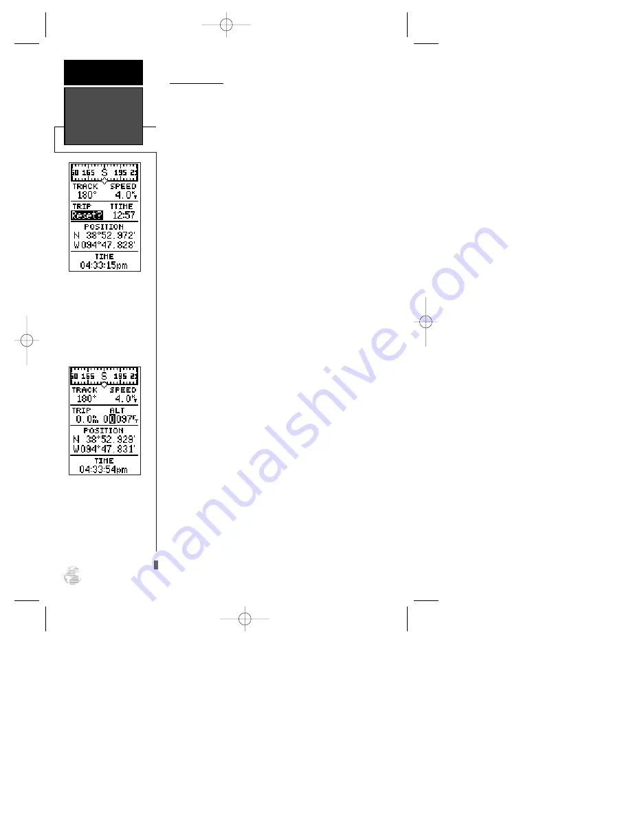
background image

Altitude Field

When the GPS 126/128 is acquiring satellites or

navigating in the 2D mode, the last known altitude is
used to compute your position. In cases where the GPS
126/128 has 2D coverage, entering your approximate
altitude will enable the receiver to determine a 3D fix.

Note: The altitude can not be changed when the

GPS 126/128 has a 3D position fix.

To enter an altitude:

1. Ensure that ‘ALT’ is displayed in the user-selectable

field.

2. Highlight the ‘ALT’ value field, and press 

F

.

3. Enter a value, and press 

F

.

Directly below the user-selectable fields is the

Position field. The position field shows the current GPS
position in latitude and longitude (default) or a user
selectable position format (see navigation setup page
47). Directly below the position field is the time.  Time
can be displayed as a 12– or– 24 hour clock (see system
setup page 46). 

Marking A Position

The GPS 126/128 allows you to mark and store up

to 500 positions as waypoints. A waypoint can be
entered by taking an instant electronic fix, by manually
entering coordinates (pg. 21), or using the bearing and
distance to a known position (pg. 22).

To mark your present position:

1. Press 

M

. The mark position page will appear,

showing the captured position and a default three-
digit name.

2. To save a default name and symbol, press 

F

to

confirm the ‘Save?’ prompt.

To enter a different waypoint name:

1. Highlight the waypoint name field, and press 

F

.

2. Make the appropriate changes, and press 

F

.

3. Highlight ‘SAVE?’, and press 

F

.

Note: To enter a different waypoint symbol or com-

ment, see pg. 23.

Altitude Field &

Marking a

Position

REFERENCE

18

Resetting the trip odome-
ter will erase the previous
mileage and set the
odometer to 0.

You may enter a known
altitude to assist the GPS
126/128 in establishing a
3D fix.

126/128 Manual (new)  6/15/98 9:51 AM  Page 18

Summary of Contents for GPS 126

Page 1: ... GPS 126 128 Marine Navigator ZOOM O w n e r s M a n u a l R e f e r e n c e GPS 126 shown 126 128 Manual new 6 15 98 9 50 AM Page 1 ...

Page 2: ...anual may be reproduced or transmitted in any form or by any means electronic or manual including photocopying and recording for any purpose without the express written permission of GARMIN Information in this document is subject to change without notice GARMIN reserves the right to change or improve its products and to make changes in the content without obligation to notify any person or organiz...

Page 3: ...nit in typical conditions Reference provides detailed explanations of advanced features and oper ations in a topical format This allows you to concentrate on a specific topic quickly without reading through sections of text that you may not need The Appendix section contains step by step instructions on how to ini tialize the unit for first time use installation instructions and items with mul tip...

Page 4: ...necessary FCC standards This equipment generates uses and can radiate radio frequency energy and if not installed and used in accor dance with the instructions may cause harmful interference to radio commu nications However there is no guarantee that interference will not occur in a particular installation If this equipment does cause harmful interference to other equipment which can be determined...

Page 5: ...electable Fields 16 Marking a Position Position Averaging Function 18 19 Waypoint Pages Managing Waypoints 19 TracBack Navigation 26 Creating and Using Routes 30 Using the Compass Highway Pages 33 Map Page Zooming Panning 37 38 Map Page Track Log Setup 39 40 Menu Page Distance Sun Calculation 43 System Setup 46 Navigation Setup 47 Interface Setup DGPS Interface 44 45 Navigation Simulator 51 Append...

Page 6: ...nac data must be acquired before GPS navigation can begin Bearing The compass direction from your position to a destination Course Made Good CMG The bearing from the active from position your starting point to your present position Crosstrack Error XTK The distance you are off a desired course in either direction Desired Track DTK The compass course between the from and to waypoints Differential G...

Page 7: ...e that passes through the north and south poles Navigation The process of traveling from one place to another and knowing where you are in relation to your desired course Position An exact unique location based on a geographic coordinate system Track TRK The direction of movement relative to a ground position Universal Transverse Mercator UTM A grid coordinate system that projects global sections ...

Page 8: ... navi gation information using degrees a measurement measured in a clockwise direction from a north reference North is described as 000º east as 090º south as 180º and west as 270º The diagram and compass rose below provide a graphic illustration of the navigation terms used by the GPS 126 128 More information on basic navigation and GPS are available at your local library or bookstore 126 128 Man...

Page 9: ...a data field s previous value B Marks your present GPS posi tion and instantly sets a return course while providing steer ing guidance I Decreases the scale of the moving map H Increases the scale of the moving map U D Selects alphanumerical characters and menu choices and moves the field highlight from field to field L R Moves the selected character field and moves the field highlight from field ...

Page 10: ...e contains a row of signal strength bars corresponding to each satellite being used Position Page The Position Page shows you where you are what direction you re heading and how fast you re going The top of the page contains a compass tape which is a graphic representation of your heading The graphic compass tape reflects your head ing only while you are moving Your track and speed are indicated i...

Page 11: ...to your desired course The upper section shows bearing and distance to the way point and your current track and speed The middle portion contains the actual highway The highway indi cates the crosstrack error or distance and direction your are off course from your waypoint Always turn in the direction the highway is pointing For example if the highway points straight up no turn is needed If the hi...

Page 12: ... use the simulator see page 51 Marking a Position To begin the tour let s take the position you have acquired either by just initializing the unit or by hav ing turned the unit on and mark it as a waypoint for future reference 1 Press the M key to capture and hold your position To mark a position you must have obtained a 2D or 3D fix or have the receiver in simulator mode If you try to mark a posi...

Page 13: ...rk position page will now be replaced by the Position Page or whatever page was displayed prior to pressing the M key The DOCK waypoint is now stored in the GPS 126 128 s memory and will remain there until you manually remove it or clear the receiver s memory For more on waypoint management see pages 19 24 Using the Position and Map Pages Now that you ve marked a position let s see how the Positio...

Page 14: ...elow the dia mond represents the position you created with the line between the two showing your track 1 Once you have reached an area that allows for gener al changes in direction without interfering in the pas sage of other boats mark your current position again and name this waypoint CHANNL See Marking a Position on page 18 2 Next make a moderate turn in any direction thats safe for navigation ...

Page 15: ...points in memory in alphabetical order 3 Use U or D to highlight the CHANNL waypoint 4 Press the F key to confirm that you want to navi gate to the displayed waypoint 5 Press the J key to view the Graphic Highway Page 11 The GOTO waypoint page allows you to select your destination from a list of all available waypoints in the GPS 126 128 s memory GETTING STARTED Going To a Waypoint Once a GOTO is ...

Page 16: ... position diamond on the CDI scale To stay on course simply steer toward the center of the highway While navigating you may decide to use the Compass Page see picture above left instead of the Highway Page To select the Compass Page 1 While viewing the Highway Page press F twice The Compass Page will now become the displayed navigation page This page provides a directional point er to your destina...

Page 17: ... the Satellite Page and also from the Menu Page see page 47 To adjust the contrast from the Satellite Page 1 Press the J or Q key until the Satellite Page appears 2 Press the arrow keypad left or right until the desired level is reached and press F Turning the Receiver Off You ve now gone through the basic operation of your new GPS receiver We encourage you to experi ment with the GPS 126 128 If y...

Page 18: ...tion by changing the orientation option on the Map Page See pg 41 for Map Setup instructions When the receiver is looking for a particular satel lite the corresponding signal strength bar will be blank and the sky view indicator will be highlighted Once the receiver has found the satellite a hollow signal strength bar will appear indicating that the satellite has been found and the receiver is col...

Page 19: ...ude 3D Diff will appear when you are receiving DGPS corrections in 3D mode Poor GPS Coverage the receiver isn t tracking enough satellites for a 2D or 3D fix Not Usable the receiver is unusable possibly due to abnormal satellite conditions Turn the unit off and back on to reset and reinitialize the receiv er if necessary Simulator the receiver is in simulator mode Screen Backlighting The GPS 126 1...

Page 20: ... 2 While holding down the M key press the P key to turn the unit on After the unit turns on release the keys A warning message will appear with Yes highlighted and ask you to confirm your selection 3 If you do not wish to erase all stored data press R and F to cancel the emergency erase 4 If you do wish to complete the emergency erase press F to confirm Position Page The second page in the GPS 126...

Page 21: ...tes since last reset Average Speed AVSPD average speed traveled Maximum Speed MXSPD maximum speed traveled since last reset Altitude ALT vertical distance above sea level To change the user selectable fields 1 Highlight the left or right user selectable field and press F 2 Use the U orD key to scroll through the avail able options 3 Press F to confirm your selection The trip odometer trip timer an...

Page 22: ...as a 12 or 24 hour clock see system setup page 46 Marking A Position The GPS 126 128 allows you to mark and store up to 500 positions as waypoints A waypoint can be entered by taking an instant electronic fix by manually entering coordinates pg 21 or using the bearing and distance to a known position pg 22 To mark your present position 1 Press M The mark position page will appear showing the captu...

Page 23: ...hese pages nearest waypoints waypoint list and waypoint definition can be accessed through the Menu Page To select a waypoint page 1 Access the Menu Page and highlight a waypoint page option 2 Press F Nearest Waypoints Page The nearest waypoints page shows the nine nearest waypoints within 100 miles of your present position with the bearing and distance noted for each waypoint This page will let y...

Page 24: ... waypoints delete way points by symbol review a waypoint or GOTO to a selected waypoint To delete all user defined waypoints 1 Highlight DELETE WPTS and press F An options page will appear asking if you want to delete all user defined waypoints or if you want to delete waypoints by symbol type 1 Highlight either ALL or SYMBOL and press F If you select ALL highlight YES and press F to confirm Neare...

Page 25: ...aypoint field and press F 3 Use the arrow keypad to scan through stored way points until desired waypoint appears see page 24 4 Press F The distance DST field will be automat ically highlighted 5 Press F Enter the desired distance 6 Press the F key To review or remove a proximity waypoint 1 Select a proximity waypoint and press F 2 Highlight REVIEW or REMOVE and press F If REVIEW is chosen the way...

Page 26: ...es you ll need to enter its bearing and distance from an existing waypoint or your present position To create a new waypoint by referencing a stored waypoint 1 From the waypoint definition page highlight NEW and press F Waypoint Definition Reference Waypoints REFERENCE 22 The GPS 126 128 s advanced waypoint plan ning features allow you to create new waypoints and practice navigation with out ever ...

Page 27: ...ion will be dis played on the map 4 Press F and select one of the following display options name with symbol symbol only or com ment with symbol 5 Press F to confirm your selection and F again to confirm the Done prompt Waypoint Comments Each waypoint stored in the GPS 126 128 has a user defined 16 character comment field The default comment is the UTC or Greenwich mean time date and time of the w...

Page 28: ...cal or alphabetical match of the character you have entered If you have more than one waypoint that begins with the same letter or number move to the next character postion and continue enter ing the waypoint name This helps eliminate the need to always enter a waypoint s complete name To scan waypoints from a waypoint field 1 Highlight the waypoint name field and press F 2 Press the left side of ...

Page 29: ...cel an active GOTO 1 Press the G key 2 Highlight CANCEL GOTO and press F Man Overboard Function The GPS 126 128 s man overboard function MOB lets you simultaneously mark and set a course to a position for quick response to passing positions To activate the MOB mode 1 Press the B key 2 Press F to begin MOB navigation The GPS126 128 will now guide you to the MOB waypoint until the MOB GOTO is cancel...

Page 30: ... Up to 30 temporary waypoints will be created to mark the most significant features of the track log in order to duplicate your exact path as closely as possible These points will be indicated by waypoint numbers begin ning with T on the waypoint list and by a T symbol on the Map Page The active route page will appear showing a route from your present position to the oldest track log point in memo...

Page 31: ...act path The receiver will then assign the 30 waypoints to the most significant points of your track and simplify segments with fewer changes in direction To save a TracBack route copy route 0 to an open storage route before activating another TracBack Activating another TracBack or storage route will overwrite the existing TracBack route Whenever a TracBack route is activated the receiver will au...

Page 32: ...own and navigated in smaller segments called legs The waypoint you are going to in a leg is called the active to waypoint and the way point immediately behind you is called the active from waypoint The line between the active to and the active from waypoint is called the active leg Whenever you activate a route the GPS 126 128 will automatically select the route leg closest to your position as the...

Page 33: ... at the top of the page with a 16 character user comment field to the right If no user comment is entered the field dis plays the first and last waypoint in the route The way point list on the left side of the page accepts up to 30 waypoints for each route with fields for desired track and distance between legs The total route distance is indicated below the waypoint list 29 Routes enable you to s...

Page 34: ...ge The process of activating or inverting a stored route takes a storage route routes 1 19 and copies it into the active route route 0 for navigation The stor age route is then no longer needed and will be retained in its original format under its existing route number This system allows you to have an active route that you may edit during navigation and save as an entirely new route from the orig...

Page 35: ...ng and Clearing Routes The route definition page is also used to copy a route to another route number This feature is useful when you make changes to the active or TracBack route and want to save the route in its modified form for future use To copy a route 1 Highlight the route number field and press F 2 Select the route number to be copied and press F 3 Highlight the copy to field and press F 4 ...

Page 36: ... GOTO At the beginning of this section we mentioned that the GPS 126 128 will automatically select the route leg closest to your position as the active leg This may mean that you are not navigating to the first waypoint in the active route If you want to select a route waypoint with which to begin navigation or you prefer to navigate a route out of sequence you can perform an on route GOTO from th...

Page 37: ...s Page provides a directional point er to the destination with a rotating compass dis play to show your direction of travel The Compass Page provides better steering guidance at slow speeds with many changes in direction where straight line navigation is not possible Both pages provide a digital display of the bearing and distance to the destination and your current speed and track over the ground...

Page 38: ...sed on current ground speed and track Course to Steer CTS the bearing which will give you the most efficient way to stay on course to your destination Crosstrack Error XTK the distance you are off the desired course in either direction This field will give you a digital representation of the CDI scale Velocity Made Good VMG the speed you are traveling toward the destination Turn TRN the amount of ...

Page 39: ... until the highway leads straight up the page Below the graphic highway is the pointer The pointer shows the direction of the waypoint relative to the direction you are moving Below the pointer are two user selectable fields If you do get off the desired course by more than 1 5th of the selected CDI range the exact distance you are off course will be displayed where the CDI scale set ting normally...

Page 40: ... you are moving For instance if the arrow points up you are going directly to the waypoint If the arrow points any direction left right down etc turn toward the arrow until it points up and then continue in that direction The bottom of the page shows two user selectable fields for ETE ETA CTS XTK VMG or TRN When you are one minute away from your destina tion based on your current speed and track o...

Page 41: ...e information The four corners of the Map Page are used to dis play various navigation data including the bearing and distance to a destination waypoint and your current track and speed over the ground The two fields at the top corners of the map show your bearing and distance to one of three selectable destinations an active destina tion waypoint a highlighted on screen waypoint or the panning ta...

Page 42: ...nd bearing from your present position to the target crosshair will appear in the upper corners of the map If you are conducting a GOTO at the time you activate the panning function the crosshair bearing and distance will replace the bear ing and distance of the GOTO waypoint As you pan around the map you ll notice that the target crosshair will point to on screen waypoints and highlight the waypoi...

Page 43: ...r 2 Select MAP POSITION and press F 3 Enter a new name symbol etc and press F You can also use the target crosshair as an instant GOTO destination This function will mark and instantly set a course for a new waypoint called MAP To GOTO the target crosshair 1 Press the G key to capture the position 2 Press the F key to confirm the MAP GOTO To save the MAP waypoint rename it as it will be overwritte...

Page 44: ...E prompt 5 Press F again on the waypoint definition page to return to the Map Page The last function you can perform with a waypoint highlighted on the Map Page is to perform a GOTO directly to the waypoint To go to a waypoint highlighted on the Map Page 1 Press G 2 Press F to confirm the GOTO waypoint page Accessing Map Setup Track Setup Windows You can access two additional pages the map setup p...

Page 45: ...d displays all route waypoint names Nearest shows the nine nearest waypoints to your position black diamond on the map Names displays the waypoint name for the nine nearest waypoints Track Log displays and plots track points on the map To turn a map item on or off 1 Highlight YES or NO for the specific map item and press F Select YES or NO and press F Track Setup Page The track setup page manages ...

Page 46: ...ing in mem ory The track log will still be stored in memory as long as the record setting is WRAP or FILL When set to on the display uses 1024 points Managing and Clearing the Track Log The rest of the track setup window displays the per centage of available memory currently used to store track log data as well as function fields to clear the track log memory and activate the TracBack feature To c...

Page 47: ...nter the des tination waypoint and press F 3 The date field will become highlighted Press F to enter the date you ll arrive at your destination and press F If you haven t marked your present position as a waypoint or you leave the to field blank the sunrise and sunset at your present position will be shown Message Page The message page is used to display all messages in the GPS 126 128 There are t...

Page 48: ... output NMEA data without any differential input capability select None NMEA DGPS Interface The last two format settings allow the differential ready GPS 126 128 to accept RTCM DGPS corrections in RTCM 104 version 2 0 format Using DGPS correc tions will improve receiver accuracy to 1 5 meters regardless of errors induced by the government s Selective Availability SA program Two RTCM options are av...

Page 49: ...ving message will be displayed If a beacon signal is tuned and no corrections are being received a No Data message will be dis played If a beacon signal cannot be tuned a No Status message will be displayed The message page will alert you to any problems relating to DGPS operation You may also monitor the DGPS status from the status field on the interface page The GPS 126 128 will display one of t...

Page 50: ...an time you will need to enter a time offset to dis play the correct local time for your area To determine the time offset for your area note your position and refer to the chart in Appendix D To enter the time offset 1 Highlight the offset field and press F 2 Enter the time offset and press F Note Move the cursor to the left to change the plus or minus sign Time Format The time display shown on t...

Page 51: ...ss F 3 To turn lighting on and off press the P briefly Navigation Setup The navigation setup submenu page is used to select units of measurement for position formats map datums CDI scale units and heading information Position Formats The default position format for the GPS 126 128 is latitude and longitude in degrees and minutes hdddºmm mmm You may also select degrees min utes and seconds hdddºmm ...

Page 52: ...r DX DY DZ DA and DF using the rocker keypad and press F 4 Highlight SAVE and press F The setup menu will reappear CDI Scale Settings The course deviation indicator CDI field lets you select the range of the CDI bar scale on the Highway Page Three scales are available 0 25 default 1 25 and 5 0 miles or kilometers Note This CDI value rep resents the full deflection of scale to either side To enter ...

Page 53: ...seconds 5 Press the F key to confirm the selection Magnetic Heading Reference The GPS 126 128 s heading information can be dis played referencing magnetic north automatic or user defined true north or calculated grid headings The default setting is automatic magnetic north which is suitable for most applications To select a heading reference 1 Highlight the heading field and press F 2 Select the d...

Page 54: ... 9 99 distance units To set the alarms 1 Move the highlight to ALARMS SETUP and press F 2 Select the desired alarm distance field and press F 3 Enter the distance for the alarm and press F 4 If you would like to change the On Off setting press the F key and use the U and D keys to turn the alarm on or off 5 Enter a setting and press the F key When setting the anchor drag alarm remember that Select...

Page 55: ...use the Position Compass or Highway Page to set your speed and track by highlighting the appropriate field entering the desired value and pressing F You may also enter a new position if you desire from the Position Page The GPS 126 128 does not track satellites in simulator mode Although you can create and save waypoints and routes while using the simulator mode never attempt to use the simu lator...

Page 56: ...e replaced by the Satellite Page with the EZinit prompt ready for you to select one of two initialization methods Select Country allows you to initialize the receiver by selecting your present position from a list of countries in the GPS 126 128 s internal data base This may speed up the initialization process AutolocateTM allows the GPS 126 128 to initial ize itself and calculate a position fix w...

Page 57: ... corner of the Satellite Page Initialization Troubleshooting If you have trouble initializing the receiver or acquiring a position check the following Does the unit have a clear view of the sky If there are large buildings or mountains nearby or if there is heavy tree cover the receiver may not be receiving enough satellite signals to calculate a position Have you selected the right country state ...

Page 58: ...should be rigid enough to support the unit and protect it from excessive vibration and shock The built in antenna has an unobstructed view of the sky To surface mount the GPS 126 1 Place the mounting bracket in the desired location 2 Mark and drill the four mounting holes for the fasten ers you are using not included 3 Fasten the bracket to the surface using the appropri ate fasteners 4 Insert the...

Page 59: ...ta cable The mounting surface should be rigid enough to support the unit and protect it from excessive vibration and shock To surface mount the GPS 128 1 Place the mounting bracket in the desired location 2 Mark and drill the four mounting holes for the fasten ers you are using not included 3 Fasten the bracket to the surface using the appropri ate fasteners 4 Insert the GPS 128 into the mounting ...

Page 60: ...e 3 From the back side of the panel loosely attach the bracket such that the slot in the ratchet area points away from the mounting panel 4 Rotate the bracket downward until the panel is pinched tightly between the units flange and bracket lobe 5 Tighten knobs and connect the power data and antenna cables Note If the panel is too thick to allow use of the supplied knobs use two M6 screws to secure...

Page 61: ...a screws directly onto any stan dard 1 x 14 thread antenna mount If you need to raise the antenna to avoid shading try using a 1 x 14 thread extension mast available at most marine dealers To install the GPS antenna 1 Screw the antenna directly onto the 1 x 14 thread mount 2 Route the cable to the mounting location of the display unit Use the appropriate tie wraps escutcheon plates and sealant to ...

Page 62: ...uropean Community Specification 529 IPX7 for protection against immer sion for 30 minutes at a depth of 1 meter With optional GARMIN GBR 21 Beacon Receiver Input Subject to accuracy degradation to 100m 2DRMS under the U S DOD imposed Selective Availability Program The GPS 126 128 is constructed of high quality materials and should not require user maintenance Should your unit ever need repair plea...

Page 63: ...ri ate harness connections To connect the GPS 126 128 to a power source 1 Connect the RED harness lead to the positive side of a 10 40 volt DC power source Make sure the power lead has an in line 1 amp fuse installed 2 Connect the BLACK harness lead to a ground strip or the negative side of a 10 40 volt DC power source To connect an external alarm connect the ground side of the alarm device to the...

Page 64: ... acquire the necessary number of satellites to compute a position Try another location with a clearer view of the sky Power Down and Re init The GPS 126 128 is not able to calculate a position due to abnormal satellite conditions Turn the unit off and verify the last position shown by other means Try the unit again later possibly in a different location Read Only Mem has Failed The permanent memor...

Page 65: ...gitudi nal zones If you are in daylight savings time add one hour to the offset Longitudinal Zone Offset Longitudinal Zone Offset W180 0º to W172 5º 12 E007 5º to E022 5º 1 W172 5º to W157 5º 11 E022 5º to E037 5º 2 W157 5º to W142 5º 10 E037 5º to E052 5º 3 W142 5º to W127 5º 9 E052 5º to E067 5º 4 W127 5º to W112 5º 8 E067 5º to E082 5º 5 W112 5º to W097 5º 7 E082 5º to E097 5º 6 W097 5º to W082...

Page 66: ...CH 1903 Switzerland Chatham 1971 Chatham 1971 Chatham Island New Zealand Chua Astro Chua Astro Paraguay Corrego Alegr Corrego Alegre Brazil Djakarta Djakarta Batavia Sumatra Island Indonesia Dos 1968 Dos 1968 Gizo Island New Georgia Islands Easter Isld 67 Easter Island 1967 European 1950 European 1950 Austria Belgium Denmark Finland France Germany Gibraltar Greece Italy Luxembourg Netherlands Norw...

Page 67: ...iian Mean Value Oman Oman Oman Ord Srvy GB Old Survey Grt Britn England Isle of Man Scotland Shetland Isl Wales Pico De Las Nv Canary Islands Potsdam Potsdam Germany Ptcairn Ast 67 Pitcairn Astro 67 Pitcairn Is Prov S Am 56 Prov So Amricn 56 Bolivia Chile Colombia Ecuador Guyana Peru Venezuela Prov S Chln 63 Prov So Chilean 63 S Chile Puerto Rico Puerto Rico Virgin Islands Qatar National Qatar Nat...

Page 68: ...eviation indicator 35 Course to Steer CTS 34 Creating Routes 30 Crosstrack Error XTK 34 D DGPS Interface 45 Date and Time 46 Deleting Waypoints 24 Distance Sun Calculations 43 E EPE 15 EZinit 16 52 Editing Routes 32 Elapsed Time ELPSD 17 Emergency Erase 16 Est Time Enroute ETE 34 Est Time of Arrival ETA 34 European Community Spec58 G GOTO 25 Getting Started Tour 11 Going To a Waypoint 11 Graphic s...

Page 69: ...ts 47 Position Page 6 16 Primary Pages 6 Proximity Waypoints 21 R Receiver Status 15 Reference Waypoints 22 Renaming Waypoints 24 Repairs 58 Route Definition Page 29 Route Navigation 28 S Satellite Page 6 14 Scanning Waypoints 24 Screen Backlighting 15 47 Screen Contrast 13 47 Signal Strength Bars 14 Simulator 51 Sky View 14 Specifications 58 Symbols 23 39 System Setup 46 T Time Format 46 Time Off...

Page 70: ... Keypad 5 Using the Position Page 9 V Velocity Made Good VMG 3 W Warranty 67 Waypoint Comments 23 Waypoint Definition 22 Waypoint List 20 Waypoint Pages 19 Waypoint Symbols 23 39 Web Site Address i Z Zooming 40 Index APPENDIX f 126 128 Manual new 6 15 98 9 52 AM Page 66 ...

Page 71: ...tained herein are exclusive and in lieu of all other warranties expressed or implied including any lia bility arising under warranty of merchantability or fitness for a par ticular purpose statutory or otherwise This warranty gives you spe cific legal rights which may vary from state to state To obtain warranty service call the GARMIN Customer Service department 913 397 8200 for a returned merchan...

Page 72: ...NOTES 126 128 Manual new 6 15 98 9 52 AM Page 68 ...

Page 73: ...126 128 Manual new 6 15 98 9 52 AM Page 69 ...

Page 74: ...he KS USA 66062 GARMIN Europe Ltd Unit 5 The Quadrangle Abbey Park Romsey UK SO51 9AQ GARMIN Asia Corp 4th Fl No 1 Lane 45 Pao Hsing Road Hsin Tein Taiwan R O C Part Number 190 00151 00 Rev A Printed in Taiwan 126 128 Manual new 6 15 98 9 52 AM Page 70 ...

Reviews: