


Installation Procedures
2-12
560-0982-01 Rev A
GNS 480 (CNX80) Installation Manual
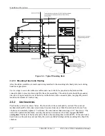
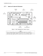
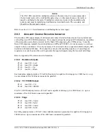
Figure 2-4 - Typical Mounting Rack
2.6.1.3 Mounting Tube Cable Routing
After the cable assemblies are made and wiring installed to the mounting tube back plate, route wiring
bundle as appropriate.
Use tie wraps to secure the cable assemblies and coax to the holes provided in the bottom of the
connector plate to provide strain relief for the cable assemblies. The cable shields should be grounded
directly to a lug mounted to one of the holes on the bottom of the connector plate, keeping the ground
leads to a maximum of 3 inches long.
2.6.2 U
NIT
I
NSERTION
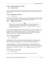
Position the cam lock as shown below. The front lobe of the cam should be vertical. The cam lock
mechanism should be fully unscrewed (turned counter-clockwise). Slide the unit into the frame. Turn
clockwise and carefully tighten (15 in-lb max.) the cam lock mechanism using a 3/32" hex driver. The
unit will be pulled into the frame, securing the unit and connectors when fully engaged.
Do NOT
overtighten.
The back of the bezel must be flush to the mounting tube (within 0.020"). If the cam lock is
hard to turn or the unit does not seat fully, the unit is probably binding and the mounting tube should be
checked.
Summary of Contents for GNS 480
Page 1: ...GNS 480 CNX80 Color GPS Nav Com Installation Manual September 2004 560 0982 01 Rev A...
Page 10: ...Table of Contents viii 560 0982 01 Rev A GNS 480 CNX80 Installation Manual NOTES...
Page 30: ...General Information 1 20 560 0982 01 Rev A GNS 480 CNX80 Installation Manual NOTES...
Page 126: ...Periodic Maintenance 6 2 560 0982 01 Rev A GNS 480 CNX80 Installation Manual NOTES...
Page 150: ...Appendix D Interconnect Diagrams D 2 560 0982 01 Rev A GNS 480 CNX80 Installation Manual NOTES...
Page 185: ......
Page 186: ......