


GTR 225/GNC 255 TSO Installation Manual
190-01182-02
Page 6-6
Rev. B
6.4.1.6 Lighting Bus 1 and Lighting Bus 2
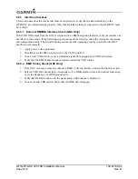
The Lighting Bus 1 and Lighting Bus 2 page (Figure 6-7) allows the installer to configure the parameters
of each lighting bus. See Table 6-5 for descriptions of each parameter.
Figure 6-7. Lighting Bus Page
Table 6-5. Lighting Bus Parameter Description
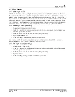
6.4.1.7 Display Information
The Display Information page (Figure 6-8) allows the installer to view and verify the display software
version, part number, serial number, minimum software level, hardware version, boot version, part number
and minimum boot version of the unit.
Figure 6-8. Display Information Pages
Selection
Description
INPUT
This setting configures the lighting bus source voltage. Select
14 VDC
,
28 VDC
,
5 VDC
, or
5 VAC
, depending on the lighting bus voltage source.
SLOPE
This setting determines how sensitive the display or bezel keys are to changes in the
lighting bus input level. Adjusting the slope higher will result in a brighter display for a
given increase in the lighting bus input level. This field has a range of 0 to 100, and is
set to 50 as the default setting.
OFFSET
This setting adjusts the lighting level up or down for any given lighting bus input level.
This field has a range of 0 (zero) to 100, and is set to 50 as a default value. This may
also be used to match lighting curves with other equipment in the panel.
Summary of Contents for GNC 255
Page 1: ...190 01182 02 March 2013 Revision B GTR 225 GNC 255 TSO Installation Manual ...
Page 2: ......
Page 137: ......
Page 138: ......