


Av. Kit Install. Manual
190-00067-62 Rev. E
Page 16
For more information on the GNC 250XL and GPS 150XL display setting see the
Display Contrast and Mode Set page and the Backlight Set page described in its Pilot's
Guide (GNC 250XL: 190-00067-60 and GPS 150XL: 190-00067-80)
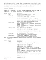
4.2.2 I/O CHANNEL 1
Select the I/O CHANNEL 1 Test Page. Change the selectable input and output to
match that of the installed equipment. The available options are:
Input:
Field
Description
off
No units connected to Channel 1 input
icarus-alt
Serial altitude received from:
Icarus, Model 3000, Mode C Serializer
shadin-alt
Serial altitude received from:
Shadin 9000T Serializer System (Non-TSO'd)
Shadin 9200T Series Serializer System (Non-TSO'd)
Shadin 8800T Series Encoder System (TSO'd)
shadin-fuel
Fuel information received from:
Shadin 91204XT Series Digital Fuel Management
System (TSO'd)
Shadin 91053XT Series Digital Fuel Management
System (TSO'd)
arnav/ei-fuel
Fuel information received from:
Arnav, Model FC-10, Fuel Computer (TSO'd)
Arnav, Model FT-10, Fuel Totalizer (TSO'd)
Electronics International, Model FP-5L, Fuel Flow
Computer (Non-TSO'd)
shadin-adc
Air data information received from:
Various models from the 9628XX-X family
shadin-fadc
Fuel/Air data information received from:
Various models from the 9628XX-X family
Note: Verify with manufacturer of data input device that unit supports GARMIN
interface.
Output: Field
Description
off
No units connected to Channel 1 output
aviation
Serial position, velocity and navigation data to:
Argus, Model 3000, Moving Map
Argus, Model 5000, Moving Map
Argus, Model 7000, Moving Map
Stormscope, Series II with Navaid, Moving Map
Shadin, 91204X[T] Digital Fuel Management System
(TSO'd)
Shadin, 91053X[T] Digital Fuel Management System
Electronics International, Model FP-5L, Fuel Flow
Computer (Non-TSO'd)
Shadin, Model 9628XX-X Fuel/Airdata Computer
(TSO'd)
GARMIN, GPS 195
GARMIN, GPS III
Summary of Contents for GNC 250
Page 24: ...Av Kit Install Manual 190 00067 62 Rev E Page 24 FIGURE 1 1 PINOUT DEFINITION 37 PIN DSUB ...
Page 26: ...Av Kit Install Manual 190 00067 62 Rev E Page 26 FIGURE 1 3A INTERCONNECT SCHEMATIC ...
Page 27: ...Av Kit Install Manual 190 00067 62 Rev E Page 27 FIGURE 1 3B INTERCONNECT SCHEMATIC ...
Page 28: ...Av Kit Install Manual 190 00067 62 Rev E Page 28 FIGURE 1 4 INTERCONNECT SCHEMATIC NOTES ...
Page 32: ...Av Kit Install Manual 190 00067 62 Rev E Page 32 FIGURE 3 3 COAX CABLE INSTALLATION ...
Page 34: ...Av Kit Install Manual 190 00067 62 Rev E Page 34 FIGURE 3 5 AVIATION RACK INSTALLATION ...
Page 42: ...Av Kit Install Manual 190 00067 62 Rev E Page 42 ...
Page 43: ...Av Kit Install Manual 190 00067 62 Rev E Page 43 ...
Page 44: ...Av Kit Install Manual 190 00067 62 Rev E Page 44 ...