


Connecting Speakers to the Amplifier
You must use the provided terminal blocks to connect speakers to the amplifier.
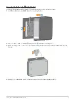
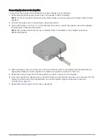
1 Route the appropriate gauge speaker wire to the speakers and the amplifier.
NOTE: It is recommended to label both ends of the speaker wire so you know which wires routes to which
speakers.
2 Connect the speaker wire to the speakers, observing polarity.
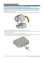
3 Using a #0 Phillips or a 3 mm (
1
/
8
in.) flat (slotted) screwdriver, connect the speaker wires to the speaker
terminal blocks, observing the polarity.
NOTE: The speaker terminal blocks are not labeled. Refer to the labels on the amplifier ports when
determining polarity.
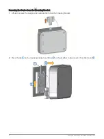
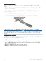
4 When all speaker wires are connected to the terminal block, press the assembled terminal block into the
appropriate ZONE port on the amplifier to complete the speaker connection for the zone.
5 Repeat the previous steps for all of the speakers you want to connect to the amplifier.
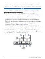
6 If you have not done so already, using a dual RCA cable, connect the RCA zone line out connectors from the
stereo to the RCA ports for the appropriate zone on the amplifier (
).
7 Repeat the previous step for each zone as necessary.
Fusion Apollo Series Installation Instructions
11