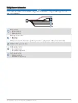

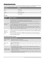


LED Power Indicator Bar Colors
The single LED power indicator bar on the front of the amplifier changes colors to indicate status and potential
faults. You can use these tables to reference the LED colors when troubleshooting the amplifier.
LED Color
Status
Off
Power off
Green
Operational
Orange
Recoverable fault
Red
Critical fault
LED is Off
Potential
Cause
Potential Resolution
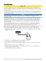
Power connec
tion issue
• Check the power wiring connections on the wiring harness and power-wire extensions, and
make sure there is a secure, waterproof connection on all wires.
• Check the connection between the wiring harness and the amplifier, and make sure it is
seated securely in the port.
• Check the power-wiring connections to the fuse or circuit breaker and to the battery and
repair or tighten any disconnected or loose wires.
• Check the circuit breaker and reset it if necessary.
• Make sure the supply voltage is within the specified operational range for the amplifier.
• Make sure you are using the appropriate gauge for the length of the power cable run, and
replace the cable with a thicker gauge, if needed.
Remote turn-
on wire
connection
issue
• Check the remote turn-on wire connection to the wiring harnesses on the amplifier and the
stereo, as well as any wire extensions, and make sure there is a secure, waterproof connec
tion on all wires.
• Make sure that the stereo and the amplifier are connected to a common power ground.
• If you connected the remote turn-on wire to a switch instead of the stereo, make sure the
switch is installed correctly.
LED is Green and There is No Sound
Potential Cause
Potential Resolution
Power or volume
issue
• Make sure the stereo is powered on.
• Make sure the volume is not set too low or muted.
DSP settings
issue
Check the DSP settings in the Fusion-Link app and make sure the correct speakers, stereo,
and amplifier are selected.
NOTE: You must select the option in the app to send the DSP settings to the devices after
you configure the settings.
Signal or speaker
connection issue
• Check the RCA cable connections to the stereo and the amplifier, and re-connect all
disconnected cables, if needed.
• Check the speaker wiring connections to the wiring harness on the amplifier and to the
speakers, as well as any wire extensions, and make sure there is a secure, waterproof
connection on all wires
• Check the wire gauge used to connect the speakers to the amplifier, and make sure it is
appropriate for the length of the wire run.
10
Fusion Apollo AP-DA214 Zone Amplifier Installation Instructions


