background image

datum and position format of the device may not match the map 

datum and position format originally used to mark the waypoint.
Position format is the way in which the GPS receiver's position 

appears on the screen. This is commonly displayed as latitude/

longitude in degrees and minutes, with options for degrees, 

minutes and second, degrees only, or one of several grid 

formats.
Map datum is a math model which depicts a part of the surface 

of the earth. Latitude and longitude lines on a paper map are 

referenced to a specific map datum.

1

Find out which map datum and position format was used 

when the original waypoint was created.
If the original waypoint was taken from a map, there should 

be a legend on the map that lists the map datum and position 

format used to create that map. Most often this is found near 

the map key.

2

Select 

Settings

 > 

Units

.

3

Select the correct map datum and position format settings.

4

Create the waypoint again.

My device does not display the correct time

Time is set by GPS position and time zone setting.

1

Select 

Settings

 > 

Units

 > 

Time Zone

.

2

Ensure the device has a GPS fix.

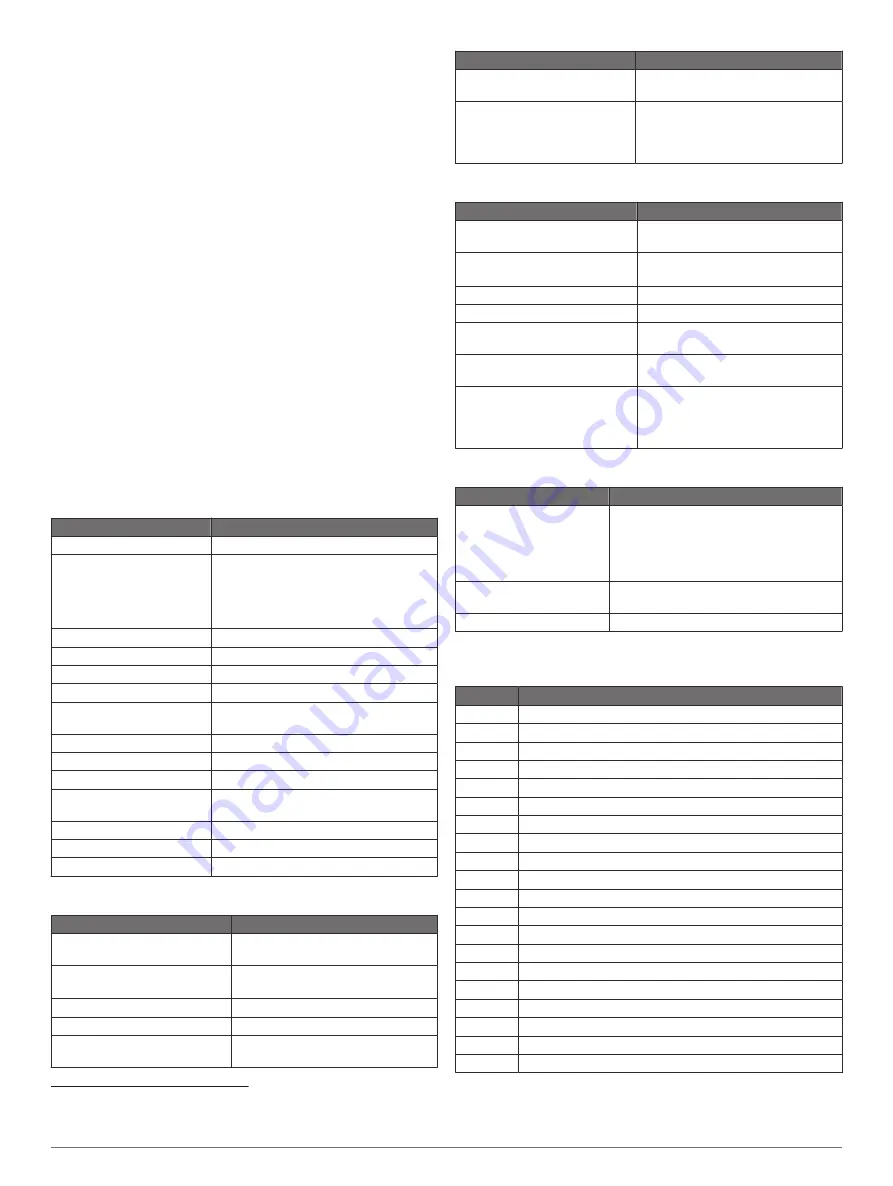
Specifications

All Models

Specification

Measurement

Material

Polycarbonate plastic

Water rating

IEC 60529 IPX7
The device withstands incidental 
exposure to water of up to 1 m for up to 
30 min. For more information, go to 

www.garmin.com/waterrating

.

Temperature range

From -15° to 55°C (from 5° to 131°F)

Input voltage

From 9 to 18 Vdc

Fuse

8 A

Compass-safe distance

65 cm (25.6 in.)

Clearance to nearest 
obstruction

150 mm (6 in.)

NMEA 2000 LEN @ 9 Vdc

1

NMEA 2000 draw

39 mA max.

Display resolution

WXGA, 1280 x 800 pixels

Memory card

2 microSD card slots; 32 GB max. card 
size

Max. waypoints

5,000

Max. routes

100

Max. active track points

50,000 points, 50 saved tracks

10-Inch Models

Specification

Measurement

Dimensions (W x H x D)

29.5 x 19.5 x 9.8 cm (11.6 x 7.7 x 
3.9 in.)

Display size (W x H)

21.7 x 13.6 cm (8.5 x 5.4 in.)
25.4 cm (10 in.) diagonal

Weight

1.8 kg (4.0 lb.)

Max. power draw

26 W

Typical current draw at 12 Vdc 
(RMS)

3 A

Specification

Measurement

Max. current draw at 12 Vdc 
(RMS)

6 A

Wireless frequencies and 
protocols

Wi

Fi, 2.4 GHz @ 17.2 dBm nominal

ANT

®

, 2.4 GHz @ 3.1 dBm nominal

Bluetooth, 2.4 GHz @ 1.2 dBm 
nominal

12-Inch Models

Specification

Measurement

Dimensions (W x H x D)

34.1 x 22.9 x 9.8 cm (13.4 x 9 x 
3.9 in.)

Display size (W x H)

26.1 x 16.3 cm (10.3 x 6.4 in.)
30.7 cm (12.1 in.) diagonal

Weight

2.5 kg (5.5 lb.)

Max. power draw

26 W

Typical current draw at 12 Vdc 
(RMS)

3.3 A

Max. current draw at 12 Vdc 
(RMS)

6.1 A

Wireless frequencies and 
protocols

Wi

Fi, 2.4 GHz @ 18.5 dBm nominal

ANT, 2.4 GHz @ 1.2 dBm nominal
Bluetooth, 2.4 GHz @ 1.0 dBm 
nominal

Sonar Models Specifications

Specification

Measurement

Sonar frequencies

1

Traditional: 50, 77, 83, or 200 kHz
CHIRP Garmin ClearVü: 260, 455, or 
800 kHz
CHIRP SideVü: 260, 455, 800, or 
1,100 kHz

Sonar transmit power 
(RMS)

2

600 W

Sonar depth

3

701 m (2,300 ft.) at 77 kHz

NMEA 0183 Information

Transmit

Sentence Description

GPAPB

APB: Heading or track controller (autopilot) sentence "B"

GPBOD

BOD: Bearing (origin to destination)

GPBWC

BWC: Bearing and distance to waypoint

GPGGA

GGA: Global positioning system fix data

GPGLL

GLL: Geographic position (latitude and longitude)

GPGSA

GSA: GNSS DOP and active satellites

GPGSV

GSV: GNSS satellites in view

GPRMB

RMB: Recommended minimum navigation information

GPRMC

RMC: Recommended minimum specific GNSS data

GPRTE

RTE: Routes

GPVTG

VTG: Course over ground and ground speed

GPWPL

WPL: Waypoint location

GPXTE

XTE: Cross track error

PGRME

E: Estimated error

PGRMM

M: Map datum

PGRMZ

Z: Altitude

SDDBT

DBT: Depth below transducer

SDDPT

DPT: Depth

SDMTW

MTW: Water temperature

SDVHW

VHW: Water speed and heading

1

Dependent upon the transducer.

2

Dependent upon the transducer rating and depth.

3

Dependent upon the transducer, water salinity, bottom type, and other water conditions.

42

Appendix

Summary of Contents for ECHOMAP Ultra 122sv

Page 1: ...ECHOMAP ULTRASERIES Owner sManual...

Page 2: ...Garmin Express Garmin LakeV Garmin Quickdraw GXM HomePort LiveScope Panoptix Reactor and SteadyCast are trademarks of Garmin Ltd or its subsidiaries These trademarks may not be used without the expres...

Page 3: ...tter 11 Basic Navigation Questions 11 Destinations 11 Searching for a Destination by Name 11 Selecting a Destination Using the Navigation Chart 12 Searching for a Marine Services Destination 12 Settin...

Page 4: ...26 Using the Race Timer 27 Setting the Distance between the Bow and the GPS Antenna 27 Laylines Settings 27 Setting the Keel Offset 27 Sailboat Autopilot Operation 27 Wind Hold 27 Tack and Gybe 28 Fo...

Page 5: ...ge Limits 37 Communications Settings 37 NMEA 0183 37 NMEA 2000 Settings 37 Wi Fi Network 37 Setting Alarms 38 Navigation Alarms 38 System Alarms 38 Sonar Alarms 38 Setting the Fuel Alarm 38 Setting th...

Page 6: ......

Page 7: ...when available Downloading the Manuals from the Web You can get the latest owner s manual and translations of manuals from the Garmin website The owner s manual includes instructions for using device...

Page 8: ...nging the Background Image 1 From the home screen select Menu Background TIP You can also adjust this setting from Settings System Display Background 2 Select an image ActiveCaptain App CAUTION This f...

Page 9: ...update 3 When you are prompted by the ECHOMAP Ultra device select an option to install the update To update the software immediately select OK To delay the update select Cancel When you are ready to i...

Page 10: ...identify proper channels and are not intended to be precisely followed Always defer to the navaids and conditions on the water when navigating to avoid groundings or hazards that could result in vess...

Page 11: ...t for a three dimensional navigation aid Fish Eye 3D Provides an underwater three dimensional view that visually represents the sea floor according to the information on the chart Fishing Charts Shows...

Page 12: ...e chart A green line attached to the target indicates the heading of the target The MMSI speed and direction of the vessel appear beneath the target if the details setting has been set to Show If the...

Page 13: ...bols Symbol Description AIS distress signal device transmission Select to see more information about the transmission and begin navigation Transmission lost Transmission test Appears when a vessel ini...

Page 14: ...time for which tides and currents are reported on the map Land POIs Shows points of interest on land Navaid Shows navigational aids such as ATONs and flashing lights on the chart Allows you to select...

Page 15: ...ed From 0 to 1 5 m from 0 to 5 ft Orange From 1 5 to 3 m from 5 to 10 ft Yellow From 3 to 4 5 m from 10 to 15 ft Green From 4 5 to 7 6 m from 15 to 25 ft Fish Eye 3D Settings NOTE This feature is avai...

Page 16: ...to the device automatically Sharing Your Garmin Quickdraw Contours Maps with the Garmin Quickdraw Community Using ActiveCaptain You can share Garmin Quickdraw Contours maps that you have created with...

Page 17: ...em a dedicated autopilot control display must be installed at each steering helm in order to disable the autopilot system NOTE Some chart views are available with premium charts in some areas To navig...

Page 18: ...as a Waypoint From any screen select Mark Creating a Waypoint at a Different Location 1 Select Nav Info Waypoints New Waypoint 2 Select an option To create the waypoint by entering position coordinate...

Page 19: ...teering to avoid land shallow water and other obstacles Creating and Saving a Route This procedure saves the route and all the waypoints in it The starting point can be your present location or anothe...

Page 20: ...the magenta line steering to avoid land shallow water and other obstacles NOTE When using Auto Guidance a gray segment within any part of the magenta line indicates that Auto Guidance cannot calculat...

Page 21: ...ation and proceed to step 10 If the Auto Guidance line is too close to known obstacles select Settings Navigation Auto Guidance Shoreline Distance Farthest If the turns in the Auto Guidance line are t...

Page 22: ...ry line You can select a boundary to act as the active boundary You can add the active boundary data to the data fields on the chart Creating a Boundary 1 Select Nav Info Boundaries New 2 Select a bou...

Page 23: ...the split frequency sonar view the two sides of the screen show a full view graph of sonar data of different frequencies NOTE The split frequency sonar view requires the use of a dual frequency trans...

Page 24: ...ws select Sonar and select a view LiveV Down Sonar View This sonar view shows a two dimensional view of what is below the boat and can be used to see a bait ball and fish Panoptix down view history in...

Page 25: ...on flashes on the ring when it is received at the depth indicated The flasher colors indicate different strengths of the sonar return The default color scheme follows a traditional sonar color palette...

Page 26: ...V sonar view 1 From the SideV sonar view select 2 Select a location on the screen 3 Select A push pin appears on the screen at the selected location 4 Select another location The distance and angle fr...

Page 27: ...avior of the buttons on the sonar screen control This is available for touchscreen devices Range Lines Shows the vertical lines indicating the distance to the right and left of the boat This setting i...

Page 28: ...reduce the effects of interference from nearby sources of noise The lowest interference setting that achieves the desired improvement should be used to remove interference from the screen Correcting i...

Page 29: ...d out of the view From a RealV sonar view select an option To adjust the viewing angle diagonally select To adjust the viewing angle horizontally select To adjust the viewing angle vertically select T...

Page 30: ...ottom When you are in deep water you can select the Points option and manually set the range to a shallower value Color Key Shows a legend of the depths the colors represent Panoptix Transducer Instal...

Page 31: ...enu Autopilot Setup Power Mode Setup Power Saver 2 Select a percentage Selecting a higher percentage reduces rudder activity and heading performance The higher the percentage the more the course devia...

Page 32: ...to use features customized for your boat type 1 Select Settings My Vessel Vessel Type 2 Select an option Sail Racing You can use the device to increase the likelihood that your boat will cross the sta...

Page 33: ...know the water depth below the keel or the lowest point of your boat and the transducer is installed at the water line or anywhere above the end of the keel measure the distance from the transducer lo...

Page 34: ...ever leave the helm unattended Learn to operate the autopilot on calm and hazard free open water Use caution when operating the autopilot near hazards in the water such as docks pilings and other boat...

Page 35: ...ling motor settings to the factory default values Assigning a Shortcut to the Trolling Motor Remote Control Shortcut Keys You can quickly open commonly used screens by assigning a shortcut key on the...

Page 36: ...al fuel in the vessel tanks select Set Total Fuel Onboard and enter the total amount of fuel in the tanks Viewing the Wind Gauges Before you can view wind information you must have a wind sensor conne...

Page 37: ...ations 4 Select a station Digital Selective Calling Chartplotter and NMEA 0183 VHF Radio Functionality When your chartplotter is connected to a NMEA 0183 VHF radio these features are enabled The chart...

Page 38: ...uency bands The default channel is 72 If you select a different channel the chartplotter uses that channel for subsequent calls until you call using another channel 1 Select Nav Info Other Vessels DSC...

Page 39: ...gion 1 From the media screen select Menu Installation Tuner Region 2 Select an option Changing the Radio Station 1 From the media screen select an applicable source such as FM 2 Select or to tune to a...

Page 40: ...9677 or go to www siriusxm ca activatexm to subscribe in Canada 4 Provide the Radio ID The activation process usually takes 10 to 15 minutes but can take up to an hour For the SiriusXM Connect Tuner...

Page 41: ...save images of the screen Menu Bar Display Shows or automatically hides the menu bar when it is not needed Background Sets the device to display a background image or color GPS Settings Select Settin...

Page 42: ...nsducer is installed at the bottom of the keel and you want to know the true depth of the water measure the distance from the transducer to the water line Enter this value in as a negative number 2 Se...

Page 43: ...hich is used to connect various NMEA 0183 devices such as VHF radios NMEA instruments autopilots wind sensors and heading sensors To connect the chartplotter to optional NMEA 0183 devices see the char...

Page 44: ...arms Fuel Set Total Fuel Onboard On 2 Enter the remaining amount of fuel that triggers the alarm and select Done Setting the Safe Zone Collision Alarm Before you can set a safe zone collision alarm yo...

Page 45: ...min device to share user data such as waypoints If the devices are mounted near each other you can connect the blue and brown wires If the devices are mounted too far apart for the wires to reach you...

Page 46: ...ards page 1 2 Wait a few moments The chartplotter opens the card management page and creates a file named GarminDevice xml in the Garmin folder on the memory card 3 Remove the memory card 4 Insert the...

Page 47: ...ellites or has been turned off for longer than a few weeks or months the device may not be able to acquire the satellites correctly Ensure the device is using the latest software If not update the dev...

Page 48: ...H x D 29 5 x 19 5 x 9 8 cm 11 6 x 7 7 x 3 9 in Display size W x H 21 7 x 13 6 cm 8 5 x 5 4 in 25 4 cm 10 in diagonal Weight 1 8 kg 4 0 lb Max power draw 26 W Typical current draw at 12 Vdc RMS 3 A Spe...

Page 49: ...nd power 130306 Wind data 130312 Temperature Transmit PGN Description 126464 Transmit and receive PGN list group function 127258 Magnetic Variance 129025 Position Rapid update 129026 COG and SOG Rapid...

Page 50: ...settings 35 distress call 31 distress signal device 7 DSC See digital selective calling E EGNOS 35 engine gauges 29 30 37 configuring 30 status alarms 30 EPIRB 7 event log 35 F factory settings 39 so...

Page 51: ...easuring distances 20 noise 20 22 overlay numbers 21 Panoptix 18 19 23 24 recording 21 scroll speed 21 sharing 20 SideV 17 source 20 surface noise 22 suspended targets 22 views 17 waypoint 20 whitelin...

Page 52: ...support garmin com August 2019 190 02536 00_0B...

Reviews: