background image

Garmin aera 795/796 Pilot’s Guide

190-01194-00  Rev. A

112

Additional Features

Overview

GPS Navigation

Flight Planning

Hazar

d A

voidance

Additional F

eatur

es

Appendices

Index

1) 

  From the map, highlight an airport using the Map Pointer.

2) 

  Touch the Map Feature Button.

3) 

  Touch the 

TERPs

 Tab (if necessary).

4) 

Touch the 

 buttons to cycle through the available Charts or touch the 

Chart Field and touch the desired Chart from the vertical list.

Displaying ChartView in Full Screen Mode:

1) 

  From the 

Main Menu

, touch 

WPT Info

 > 

TERPs

 (if necessary)

.

2) 

With the desired chart displayed touch 

TERPs

 again.

3) 

Touch the


icon 

to exit Full Screen Mode.

When a terminal procedure chart is not available for the requested airport or there 

is an error rendering the data, the banner "CHART NOT AVAILABLE” appears on 
the screen.  The "CHART NOT AVAILABLE” banner does not refer to the ChartView 
subscription, but rather the availability of a particular airport chart selection or 
procedure for a selected airport.

Chart Not Available Banner

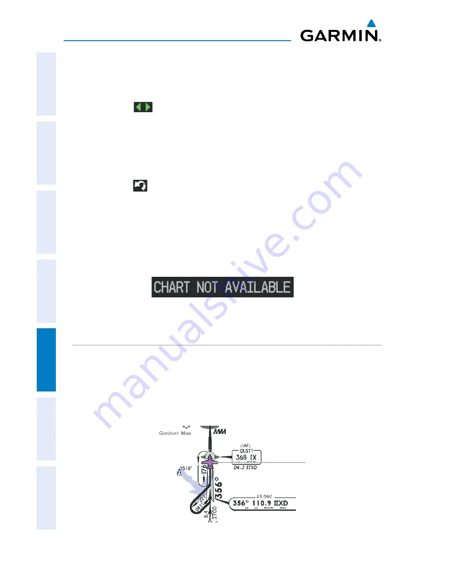
AIRCRAFT SYMBOL

The aircraft symbol is shown in magenta on the chart only if the chart is to scale 

and the aircraft position is within the boundaries of the chart.  The aircraft symbol is 
not displayed when the Aircraft Symbol Not Shown Icon (X over the aircraft symbol) 
appears in the lower right corner.  The Aircraft Symbol Not Shown Icon may appear at 
certain times (e.g., a loss of GPS), even if the chart is displayed to scale.  

Aircraft Symbol Displayed on Chart (Waypoint Page)

Single Display

Aircraft 

Position on 

Chart

Summary of Contents for aera 796

Page 1: ...models 795 and 796 Pilot s Guide...

Page 2: ......

Page 3: ...OVERVIEW GPS NAVIGATION FLIGHT PLANNING HAZARD AVOIDANCE ADDITIONAL FEATURES APPENDICES INDEX...

Page 4: ......

Page 5: ...ransmitted disseminated downloaded or stored in any storage medium for any purpose without the express written permission of Garmin Garmin hereby grants permission to download a single copy of this ma...

Page 6: ...displayed minimum safe altitudes MSAs are only advisory in nature and should not be relied upon as the sole source of obstacle and terrain avoidance information Always refer to current aeronautical ch...

Page 7: ...er the pilot must recognize that providing monitoring and or self test capability for all conceivable system failures is not practical Although unlikely it may be possible for erroneous operation to o...

Page 8: ...the device outside of the following temperature range from 4 to 131 F from 20 to 55 C Contact your local waste disposal department to dispose of the device battery in accordance with applicable local...

Page 9: ...n accordance with California s Proposition 65 If you have any questions or would like additional information please refer to our web site at www garmin com prop65 NOTE Interference from GPS repeaters...

Page 10: ...Garmin aera 795 796 Pilot s Guide 190 01194 00 Rev A Blank Page...

Page 11: ...tional 10 Main Menu 11 1 4 Menus and Data Entry 15 Option Menus 15 Data Entry 15 1 5 Using Map Displays 18 Map Range 18 Map Panning 20 Map Overlays 22 Map Symbols 22 1 6 System Settings 23 Display 24...

Page 12: ...1 Introduction 65 Data Fields 66 3 2 Flight Plan Creation 67 Adding Waypoints to an Existing Flight Plan 69 3 3 Flight Plan Storage 70 3 4 Flight Plan Activation 70 3 5 Flight Plan Editing 71 Editing...

Page 13: ...piration Date 117 5 5 VFR IFR Chart Viewing 117 5 6 SafeTaxi 118 SafeTaxi Cycle Number and Revision 119 5 7 SiriusXM Radio aera 796 119 Activating SiriusXM Satellite Radio Services 120 Using SiriusXM...

Page 14: ...3 TIS vs TAS TCAS 153 TIS Limitations 153 Appendix G Utilities 157 Document Viewer 157 Scratch Pad 157 Flight Log 158 Track Log 160 Heading Line 163 E6B Calculator 164 Aircraft Profile 166 Weight Bala...

Page 15: ...res Appendices Index SECTION 1 OVERVIEW 1 1 UNIT OVERVIEW The aera 795 796 presents GPS derived analog flight instrumentation position navigation and hazard avoidance information to the pilot using a...

Page 16: ...ttery installed when the unit is on WARNING The product contains a lithium ion battery To prevent damage remove the unit from the aircraft or store it out of direct sunlight Installing the battery 1 L...

Page 17: ...dices Index Battery Release Push to remove the battery Unit Overview Back Battery Out Power Button SD Card Slot Battery Contacts CHARGING THE BATTERY NOTE While in Charge Mode the unit draws a current...

Page 18: ...so that it does not interfere with aircraft operation The unit begins charging as soon as external power is applied USING CHARGE MODE Applying external power to the aera 795 796 automatically turns on...

Page 19: ...ure proper initialization the aera 795 796 is shipped from the factory inAutoLocate mode which allows the receiver to find itself anywhere in the world Duringinitialization currentdatabaseinformationi...

Page 20: ...atellites visible at its last known or initialized location but has not acquired a fix 2D GPS Location At least three satellites have been acquired and a two dimensional location fix has been calculat...

Page 21: ...nished acquisition SATELLITE INFORMATION Satellites currently in view are shown at their respective positions on a satellite constellation diagram The outer circle of the constellation diagram represe...

Page 22: ...in either Portrait or Landscape Mode Changing the display orientation 1 From the Main Menu touch Tools Setup Display Or Press the Power Button once quickly 2 Touch the Display Orientation datafield to...

Page 23: ...tures Appendices Index SCROLLING AND PANNING Scrolling and panning on the touchscreen Drag up or down to scroll menus documents etc Or Drag in any direction to pan maps or charts Scrolling Panning ZOO...

Page 24: ...ion menu Direct to Displays the Direct to function NRST Displays the Nearest Icons Touch and hold to quickly access the nearest airports PAGE BUTTONS OPTIONAL NOTE The aera 795 796 Optional Page Butto...

Page 25: ...ap View Terrain Displays the Terrain View 3D Vision Displays 3D Vision WPT Info Displays the Waypoint Information FPL List Displays the Flight Plan List Active FPL Displays the Active Flight Plan Numb...

Page 26: ...ays nearest ARTCCs Air Route Traffic Control Centers FSS Displays nearest Flight Service Stations FSS Airspace Displays nearest airspace WEATHER ICONS aera 796 From the Main Menu touch the Weather ico...

Page 27: ...ys Surface Pressure Sea Temp Displays Water Temperature TOOLS From the Main Menu touch the Tools Icon to access the second level Tools icons Touch the following second level icons to display the assoc...

Page 28: ...he third level Setup Icons Touch the following third level icons to perform the associated function Display Displays backlight intensity timeout and color mode settings Sound Displays sound settings U...

Page 29: ...ated Icon that displays a context sensitive list of menu options available Navigating the option menu Touch the Icon Touch the desired menu option DATA ENTRY DATA ENTRY ICONS The following icons are d...

Page 30: ...erview GPS Navigation Flight Planning Hazard Avoidance Additional Features Appendices Index Entering alphanumeric data When alphanumeric data can be entered a keypad will appear after touching the des...

Page 31: ...ndices Index Entering predetermined data options Touch the Data Option Button to display a vertical list of data options if applicable or to toggle two data options i e On Off Or Touch the buttons to...

Page 32: ...rmation Airports NAVAIDs airspaces airways land data highways cities lakes rivers borders etc with names Map Pointer information distance and bearing to pointer location of pointer name and other pert...

Page 33: ...p Range Overzoom Scale Bar Rep resenting a Map Scale of 3 nm Per Scale Width AUTO ZOOM Auto Zoom allows the aera 795 796 to change the map display range to the smallest range clearly showing the activ...

Page 34: ...nter or the object s airports obstacles etc elevation if known When the Map Pointer is over a map feature the map feature is highlighted an information box appears on the map and the highlighted map f...

Page 35: ...e on the map to activate the map pointer When the Map Pointer is over a map feature the map feature is highlighted an information box appears on the map and the highlighted map feature is displayed on...

Page 36: ...touch Map Menu Show Hide 2 Touch the Show Hide Data Option Button for the desired overlay MAP SYMBOLS Refer to Appendix H for a list of map symbols DECLUTTER The map can be adjusted to declutter remo...

Page 37: ...egory 3 Touch Detail Level Data Option Button and touch the desired option from the list Least Less Normal More or Most 1 6 SYSTEM SETTINGS The third level Setup Icons allow management of the followin...

Page 38: ...e Display Orientation datafield to select Portrait or Landscape PAGE BUTTONS Configuring the Page Buttons 1 Main Menu touch Tools Setup Display Choose Buttons 2 Touch one of the available Page Buttons...

Page 39: ...ays On 15 Seconds 30 Seconds 1 Minute or 2 Minutes ZOOM BUTTONS Displaying removing the Zoom Buttons 1 From the Main Menu touch Tools Setup Display 2 Touch the Show Hide Data Option Button for the Zoo...

Page 40: ...re a percentage of the Master sound Alerts refers to navigation phrases e g Pull Up and Media refers to the XM radio volume The Terrain Audio and Key Tones can also be toggled On Off Adjusting the sou...

Page 41: ...a vertical list is displayed with a blue outline around the current setting Touch the or buttons to increase decrease the numerical values if necessary 4 Touch and hold to return to the Main Menu Ico...

Page 42: ...e type including water landing facilities Minimum Runway Length allows the pilot to enter a specific length for the shortest runway allowed Entering airport criteria 1 Touch NRST Airport Menu Set Airp...

Page 43: ...the Main Menu touch Tools Position Menu New Location 2 Touch Automatic The GPS will attempt to figure out the new location Entering a new location 1 From the Main Menu touch Tools Position Menu New Lo...

Page 44: ...Simulator Mode From the Main Menu touch Tools Position Menu Start Stop Simulator Adjusting the simulated altitude track speed waypoint posi tion 1 From the Main Menu touch Tools Position Menu Start S...

Page 45: ...s North Up NORTH UP Track Up TRK UP or Desired Track Up DTK UP An aircraft icon is placed on the Navigation Map at the location corresponding to the calculated present position The aircraft position a...

Page 46: ...dex DATA FIELDS The data fields on the Navigation Map can be independently configured by the user Data Fields Navigation Map Data Fields By default the Data Fields are set to display Ground Speed GS D...

Page 47: ...dditional Features Appendices Index Changing the information shown in the data fields From the Main Menu touch the Map Icon Touch the Menu Icon Touch the Change Data Fields menu option Touch the desir...

Page 48: ...En Route Safe Altitude ESA Flight Timer FLT TIMER Fuel Timer Glide Ratio G R Ground Speed GS Ground Track TRK Minimum Safe Altitude MSA Next Waypoint NEXT WPT Sunrise Sunset Time En Route Destination...

Page 49: ...n be independently configured by the user Accessing numeric flight data From the Main Menu touch Numbers Changing numeric flight data fields 1 From the Main Menu touch Numbers 2 Touch the desired data...

Page 50: ...heading reference User Selected or Off NOTE The Compass Arc is hidden while on the ground Compass Arc Navigation Map Magenta Bug Indicator Compass Arc Displaying Removing the Compass Arc from the Nav...

Page 51: ...shows a graphic Horizontal Situation Indicator HSI surrounded by additional indicators The graphic HSI depicts the course to the destination or the next waypoint in a flight plan current ground track...

Page 52: ...within 2 nm of the FAF or MAP CDI scale 5 0 if the previous two conditions do not exist Displaying Removing the HSI Panel 1 From the Main Menu touch Map Menu Show Hide 2 Touch the Show Hide Button in...

Page 53: ...From the Main Menu touch the Map or the Active FPL Icon 2 Touch the Menu icon 3 Touch the Release Hold menu option only available when navigating a Direct To or Flight Plan 2 3 VERTICAL NAVIGATION VNA...

Page 54: ...de the Approaching Target Altitude message appears the EstimatedTimeToVNAV goes blank and theVNAV indicator disappears from the HSI CAUTION The aera 795 796 is aVFR navigation tool and should not be u...

Page 55: ...t defines the target location Profile Enter the descent rate Altitude Enter the desired reference waypoint altitude Select Above Waypoint to use field elevation for airports in the Jeppesen database o...

Page 56: ...when navigating a Direct To or Flight Plan VNAV Indicator Panel VNAV Indicator 2 4 MAP DISPLAY SETUP Map displays are used extensively in the aera 795 796 to provide situational awareness in flight T...

Page 57: ...NOTE The Map Orientation setting only affects the Navigation Map Terrain Map and the 3D Vision Map NOTE The Compass Arc will change depending on the Map Orientation selected i e North Up No Compass Ar...

Page 58: ...upward to 45 000 feet MSL altitudes above 18 000 feet are called flight levels and are described as FL450 for 45 000 feet MSL Jet Routes are designated with a J before the route number Low Altitude Ai...

Page 59: ...796 will choose the most appropriate identifier based on the current position and phase of flight Waypoint Information Info Tab Waypoint Identifier Button Info Tab Bearing Distance Waypoint Identifier...

Page 60: ...Touch the Search Button between the c Enter the desired data using the keypad If duplicate entries are displayed touch the desired duplicate from the list d Touch OK Or a Touch the buttons to cycle th...

Page 61: ...ge becomes 0 2 nm and centers on the desired runway Touch the Runway Button again to return to the previous map range WAYPOINT FREQUENCIES Selecting additional information for a frequency 1 From the M...

Page 62: ...d If duplicate entries are displayed touch the desired duplicate from the list d Touch OK Or a Touch the buttons to cycle through the waypoint categories Flight Plan Waypoints Nearest Airports or Rece...

Page 63: ...t a Touch the buttons to display the desired search option on the Search Button Search by Identifier Search by Facility Name Search by City Search by Address only available with the optional City Navi...

Page 64: ...HF Omnidirectional Radio Beacon facility name identifier facility type symbol bearing distance and frequency NDB Non Directional Beacons identifier facility type symbol bearing distance and frequency...

Page 65: ...define the minimum runway length and surface type used when determining the 15 nearest airports to display A minimum runway length and or surface type can be entered to prevent airports with small ru...

Page 66: ...with the optional City Navigator data b Touch the Search Button between the c Enter the desired data using the keypad If duplicate entries are displayed touch the desired duplicate from the list d To...

Page 67: ...e Main Menu touch the Map Icon 2 Touch the desired METAR Flag If the METAR flags are not displayed adjust the settings from the Set Up Map menu option 3 Touch the Map Feature Button with the desired i...

Page 68: ...for VORs NDBs Intersections User Waypoints Cities ARTCCs FSSs and Airspace can be viewed by touching the WPT Info Icon the NRST Icon or by using the Map Pointer Additional Information Airport VOR NDB...

Page 69: ...1 Touch NRST Intersection 2 Touch the desired Nearest Intersection twice The intersection information is displayed 3 If desired touch Menu Show Map or Show Chart Or 1 From the Main Menu touch the Map...

Page 70: ...mation function the Nearest function or the Map Panning function The Nearest VOR function can be used to quickly find a VOR close to the flight path The list only includes VORs that are within 200nm L...

Page 71: ...S The aera 795 796 can create and store up to 3 000 user defined waypoints Once a waypoint has been created it can be renamed deleted or moved User Waypoints Creating user waypoints 1 Touch the desire...

Page 72: ...y symbol or delete by distance a Touch the desired User Waypoint b Touch Menu c Touch the Delete Waypoint menu option The confirmation window will appear Or a Touch the Menu Icon b Touch the Delete Al...

Page 73: ...ist Or 1 From the Main Menu touch Map 2 Touch the desired city symbol on the map 3 Touch the Map Feature Button with the desired city displayed refer to the Overview Section on Map Panning for more in...

Page 74: ...requencies are displayed AIRSPACE The Nearest Airspace function and Airspace Alerts provide information about airspaces and the location of the aircraft in relationship to them The NearestAirspace fun...

Page 75: ...ssage which includes the airspace name time to entry if applicable and status Touch the message to acknowledge it NOTE Airspace Alert Messages do not work while on the ground There are four types of s...

Page 76: ...Touch the desired On Off Button s Airspace Alert Message Smart Airspace SmartAirspace shows airspace at and immediately surrounding the aircraft s current altitude in bold Airspaces at all other alti...

Page 77: ...arby airport Once a direct to is activated the aera 795 796 establishes a point to point course line from the present position to the selected direct to destination Course guidance is provided until t...

Page 78: ...on if necessary Selecting a nearby airport as a direct to destination 1 Touch NRST Airport 2 Touch the desired nearest airport 3 Touch Direct To 4 Touch Activate Selecting a waypoint as a direct to de...

Page 79: ...and the system is turned off When storing flight plans with an approach the aera 795 796 uses the waypoint information from the current database to define the waypoints If the database is changed or u...

Page 80: ...rmation shown in the flight plan data fields 1 From the Main Menu touch the Active FPL Icon Or a From the Main Menu touch FPL List b Touch the desired Saved Flight Plan from the list An option menu ap...

Page 81: ...ight plans available for activation becomes the active flight plan Active Flight Plan Active Leg Active Leg Data Fields Creating an active flight plan 1 From the Main Menu touch the Active FPL Icon 2...

Page 82: ...he Main Menu touch FPL List Menu New Flight Plan 2 Touch the Touch to add Waypoint Button 3 Enter the desired waypoint a Touch the buttons to display the desired search option on the Search Button Sea...

Page 83: ...earch by Identifier Search by Facility Name Search by City Search by Address only available with the optional City Navigator data or Search by Crossroads only available with the optional City Navigato...

Page 84: ...ight Plan menu option A confirmation window appears 3 Touch Yes A copy of the flight plan is stored in the next available position in the Flight Plan List 3 4 FLIGHT PLAN ACTIVATION Activating a store...

Page 85: ...ing the Flight Plan cruise speed and fuel flow From the Main Menu touch Active FPL and touch the Fuel Flow Button to enter the desired fuel flow using the keypad Or 1 From the Main Menu touch Tools Pr...

Page 86: ...FLIGHT PLANS Individual or all stored flight plans can be deleted from the aera 795 796 memory Deleting a stored flight plan While reviewing the desired Stored Flight Plan touch the Menu Delete Flight...

Page 87: ...de to the active flight plan affect navigation as soon as they are entered Editing the active flight plan does not affect any saved flight plans Waypoints in the final approach segment such as the FAF...

Page 88: ...h aircraft control is based solely upon flight instruments The approaches provided are for monitoring purposes only Only the final course segment final approach fix FAF to missed approach point MAP of...

Page 89: ...r ILS and only the final course segment final approach fix to missed approach point of the published approach is available in the aera 795 796 If the airport does not have a published approach the Sel...

Page 90: ...Approach menu option only available when navigating a flight plan A vertical list of available approaches is displayed 3 Touch the desired approach The Vectors to Final window appears 4 Touch Yes or N...

Page 91: ...final course beyond the final approach waypoint in the database final approach fix FAF A Vector to Final symbol appears beside the first approach waypoint in the Active Flight Plan Activating Cancelli...

Page 92: ...Garmin aera 795 796 Pilot s Guide 190 01194 00 Rev A 78 Flight Planning Overview GPS Navigation Flight Planning Hazard Avoidance Additional Features Appendices Index Blank Page...

Page 93: ...iriusXM SatelliteWeather can be used the service must be activated Service is activated by providing SiriusXM Satellite Radio with a Radio ID unique to the GXM 40 antenna SiriusXM Satellite Radio uses...

Page 94: ...RAD NEXt generation RADar is a network of 158 high resolution Doppler radar systems that are operated by the NationalWeather Service NWS NEXRAD data provides centralized meteorological information for...

Page 95: ...e the weather severity level The display of radar coverage is always active when NEXRAD is selected Areas where NEXRAD radar coverage is not currently available or is not being collected are indicated...

Page 96: ...nd 55 N is unknown NEXRAD Intensity Colors are used to identify the different NEXRAD echo intensities reflectivity measured in dBZ decibels of Z Reflectivity designated by the letter Z is the amount o...

Page 97: ...ops Altitudes WINDS ALOFT Winds Aloft data shows the forecasted wind speed and direction at the surface and at selected altitudes Altitudes can be displayed in 3 000 foot increments up to 42 000 feet...

Page 98: ...er region and within the last seven minutes The exact location of the lightning strike is not displayed Lightning Data STORM CELLS The Storm Cells feature displays storms as well as the storm s projec...

Page 99: ...wind precipitation cloud cover cloud heights visibility and barometric pressure They can also contain information on precipitation amounts lightning and other critical data If METAR data is available...

Page 100: ...nter The METAR flag color is determined by the information in the METAR text VFR ceiling greater than 3000 feet AGL and visibility greater than 5 miles Marginal VFR ceiling 1000 3000 feet AGL and or v...

Page 101: ...her conditions AIRMETs are displayed as colored dashed lines AIRMET Selected Additional AIRMET Data SIGMETS A SIGMET SIGnificant METeorological Information advises of weather that is potentially hazar...

Page 102: ...ilitary depots and forest fires TFRs are represented as an area highlighted by red active or yellow not yet active TFR Data Selected Additional TRF Information PIREPS Pilot Weather Reports PIREPs prov...

Page 103: ...ontours for the lowest forecast altitude where icing conditions are likely to occur Freezing Level Data TURBULENCE FORECAST Turbulence data identifies the potential for erratic movement of high altitu...

Page 104: ...not a forecast but a representation of the current conditions at the time of the analysis Supercooled Large Droplet SLD icing conditions are characterized by the presence of relatively large super coo...

Page 105: ...re displays pressure isobars and pressure centers The isobars connect points of equal pressure Pressure readings can help determine weather and wind conditions High pressure areas are generally associ...

Page 106: ...e display If a map range larger than the weather product map range setting is selected the weather product data is removed from the map For weather products such as Lightning and Storm Cells the weath...

Page 107: ...riusXM Weather products on the Weather Map 1 From the Main Menu touch the Weather Icon 2 Touch the desired second level Weather Icon 3 If necessary touch the buttons to scroll through the list of avai...

Page 108: ...Touch the Set Up Map menu option 4 Touch the buttons to select the Weather Category 5 Touch the desired setting to change 6 Touch the buttons if available to select the desired settings or touch the O...

Page 109: ...d Or a From the Main Menu touch the Weather Icon b Touch the NEXRAD Icon or the Satellite Icon 2 Touch the Menu Icon 3 Touch the Animate Weather menu option 4 2 TERRAIN WARNING Do not use Terrain info...

Page 110: ...f the surrounding terrain and obstacles relative to the position and altitude of the aircraft GPS position and GPS MSL altitude are used to calculate and predict the aircraft s flight path in relation...

Page 111: ...L Unlighted Obstacle Lighted Obstacle Potential Impact Points Obstacle Location 1000 AGL 1000 AGL 1000 AGL 1000 AGL WARNING Red obstacle is above or within 100 below current aircraft altitude CAUTION...

Page 112: ...ERRAIN VIEWS Two terrain views can be displayed Map with Profile or Map Only Changing the terrain view 1 From the Main Menu touch the Terrain Icon 2 Touch the Menu Icon 3 Touch the Select Page Layout...

Page 113: ...e you reach the terrain or obstacle Alert Sensitivity The three Alert Sensitivity settings Terrain Obstacle and Descent Rate determine what level of alerts are annunciated The aera 795 796 defaults to...

Page 114: ...rough 500 feet above the destination airport an audible Five Hundred altitude reminder occurs The Terrain Alert Annunciation is shown to the lower left corner of the screen If the Terrain Map is not d...

Page 115: ...configuration information The aera 795 796 supports TIS input from a Garmin Mode S transponder such as the GTX 330 TIS SYMBOLOGY TIS traffic is shown according to TCAS symbology graphically shown on...

Page 116: ...udio alert is sounded The TIS audio alert is also generated whenever TIS service becomes available The following TIS audio alerts are available Traffic TIS traffic alert received Traffic Not Available...

Page 117: ...c can be displayed on the Navigation Map Adjusting TIS settings on the navigation map 1 From the Main Menu touch Map Menu Set Up Map 2 Touch the buttons to select the Map Category 3 Touch TIS Traffic...

Page 118: ...Garmin aera 795 796 Pilot s Guide 190 01194 00 Rev A 104 Hazard Avoidance Overview GPS Navigation Flight Planning Hazard Avoidance Additional Features Appendices Index Blank Page...

Page 119: ...Taxi and FliteCharts in electronic form it is still advisable to carry another source of charts on board the aircraft The following additional features are included with the aera 795 and or 796 depend...

Page 120: ...will cause 3D Vision to be disabled until it is restored The 3D Vision terrain display shows land contours colors are consistent with those of the topographical map display large water features tower...

Page 121: ...ing 3D Vision Page Layout From the Main Menu touch 3D Vision Menu Select Page Layout Setting the 3D Vision Bug Indicator From the Main Menu touch 3D Vision Menu Set Bug Indicator Changing the informat...

Page 122: ...Garmin aera 795 796 Pilot s Guide 190 01194 00 Rev A 108 Additional Features Overview GPS Navigation Flight Planning Hazard Avoidance Additional Features Appendices Index 3D Vision...

Page 123: ...isplay the desired search option on the Search Button Search by Identifier Search by Facility Name Search by City Search by Address only available with the optional City Navigator data or Search by Cr...

Page 124: ...al Features Overview GPS Navigation Flight Planning Hazard Avoidance Additional Features Appendices Index Airport Directory Data Airport Identifier Field Service Icon Icon Description Restaurant on Fi...

Page 125: ...T Info TERPs Tab if necessary 2 Touch the Waypoint Identifier Button top of page 3 Enter the desired waypoint a Touch the buttons to display the desired search option on the Search Button Search by Id...

Page 126: ...not available for the requested airport or there is an error rendering the data the banner CHART NOT AVAILABLE appears on the screen The CHART NOT AVAILABLE banner does not refer to the ChartView sub...

Page 127: ...apart zoom in JEPPESEN DATABASE PUBLISHED NOTAMS NOTE Only NOTAMs for the selected airport are shown when available There may be other NOTAMs available pertaining to the flight that may not be displa...

Page 128: ...ouch WPT Info TERPs Tab if necessary 2 Touch the Waypoint Identifier Button top of page 3 Enter the desired waypoint a Touch the buttons to display the desired search option on the Search Button Searc...

Page 129: ...the vertical list Displaying FliteCharts in Full Screen Mode 1 From the Main Menu touch WPT Info TERPs if necessary 2 With the desired chart displayed touch TERPs again 3 Touch the icon to exit Full S...

Page 130: ...raft symbol is not displayed when the Aircraft Symbol Not Shown Icon appears The Aircraft Symbol Not Shown Icon may appear at certain times even if the chart is displayed to scale Aircraft Symbol Disp...

Page 131: ...rts 3 Touch Menu The Chart Type Menu is displayed 4 Touch the desired chart type VFR IFR Low IFR High or TERPs Activating the chart pointer on a VFR IFR chart While viewing a Chart touch anywhere on t...

Page 132: ...he airport on the Navigation Map Designated Hot Spots are recognized at airports with many intersecting taxiways and runways and or complex ramp areas Airport Hot Spots are outlined to caution pilots...

Page 133: ...be found from the Main Menu by touching the Tools Database The SafeTaxi database is provided by Garmin Refer to Appendix C for instructions on updating the SafeTaxi database 5 7 SiriusXM RADIO aera 7...

Page 134: ...adio uses the Radio ID to send an activation signal that when received by the GXM 40 allows it to play entertainment programming Refer to the GXM 40 Owner s Manual for more information on activating S...

Page 135: ...f the audio entertainment features of the SiriusXM Satellite Radio Category Field Button Category Navigation Active Channel SiriusXM Radio Overview Channel List CATEGORY The Category Field cycles thro...

Page 136: ...ls for the selected category The active channel is outlined blue in the Channel List Selecting a channel from the channel list 1 Scroll through the Channel List by touching and dragging the list up do...

Page 137: ...l Features Appendices Index Tune Button Channel Number Entry Plus Button Minus Button USING FAVORITES Favorites is a customized category of up to 30 of your SiriusXM Radio favorites To add a channel t...

Page 138: ...ugh the horizontal category list until the Favorites Category is displayed Or Touch and hold the Category Button 3 Scroll through the Channel List by touching and dragging the list up down 4 Touch the...

Page 139: ...ume refers to system alerts TIS Terrain and the Media volume refers to SiriusXM radio volume Adjusting the volume 1 From the Main Menu touch the SiriusXM Icon 2 Touch the Menu Icon 3 Touch the Volume...

Page 140: ...6 checklists and thus cannot be responsible for the availability and or content NOTE Checklists cannot be edited from within the system The aera 795 796 is capable of displaying checklists which allow...

Page 141: ...or more databases was found Can t Unlock Maps No applicable unlock code for one or more maps was found All MapSource maps are not accessible Check XM Antenna Internal problem with the GXM antenna Cont...

Page 142: ...nt Memory Full No additional route waypoints can be saved Steep Turn Ahead Approaching a turn that requires a bank angle in excess of 25 degrees to stay on course Track Already Exists A saved track wi...

Page 143: ...uracy The current accuracy of the GPS determined location Altitude The current altitude in geometric height above Mean Sea Level MSL Bearing The compass direction from the present position to a destin...

Page 144: ...The next waypoint in the flight plan or direct to route Sunrise The time at which the sun rises on this day current location Sunset The time at which the sun sets on this day current location Estimate...

Page 145: ...usly selected VNAV position and altitude based upon current groundspeed Weather Altimeter aera 796 The altimeter setting at the nearest METAR reporting station Weather Dew Point aera 796 The dew point...

Page 146: ...parameters that are set within the software algorithms and are dependant on the sensitivity level set in the Terrain Setup Menu Alert Severity Terrain Obstacle Descent Rate Caution caution terrain ca...

Page 147: ...en the aera 795 796 loses the GPS signal for any reason the following will occur A blinking red question mark will appear over the airplane icon on the map The Lost Satellite Reception message will di...

Page 148: ...ur aera 795 796 SD Cards are not waterproof They should not be exposed to moisture or excessive static charges and should be stored in the case supplied with the card Installing an SD Card 1 Insert th...

Page 149: ...a 795 796 depending on the unit Americas Atlantic or Pacific See the Additional Features section for information on Airport Directory FliteCharts and SafeTaxi See the Hazard Avoidance section for info...

Page 150: ...VFR Charts The IFR VFR Chart database contains Sectionals Hi Altitude Low Altitude World Aeronautical Charts WAC and Terminal Aera Charts TAC This database is updated on a 28 day cycle SafeTaxi The Sa...

Page 151: ...aera 795 796 includes an internal Jeppesen database that provides location and facility information for thousands of airports VORs NDBs and more Updates to the Jeppesen database are available every 28...

Page 152: ...ogy used for NDBs VORs and airports is consistent with those used on a sectional chart NOTE After performing a Jeppesen database update verify all flight plan routes are current If there is an obsolet...

Page 153: ...aircraft s operating controls and safety devices or cause damage or personal injury in the event of an accident or turbulence Do not mount the aera 795 796 where the pilot or passengers are likely to...

Page 154: ...idance Additional Features Appendices Index Attaching the yoke mount assembly to the aera cradle Join the yoke mount assembly to the aera cradle using the provided screws 4 ea nuts 4 ea and washers 8...

Page 155: ...g figure 1 Open the clamp by turning the Clamp Adjustment Knob until it can be easily placed over the yoke shaft or control arm Install the yoke mount as far from the panel as is practical 2 When in p...

Page 156: ...e until it snaps into place Attaching the aera landscape orientation to the yoke mount 1 Fit the bottom of the aera into the cradle 2 Tilt the aera back until it snaps into place Removing the aera fro...

Page 157: ...he memory card slot Press it in until it clicks 2 Turn the aera 795 796 on 3 Connect the small end of the USB cable to the USB connector on the unit 4 Connect the larger end of the USB cable to a USB...

Page 158: ...omm and the SL40 comm NOTE For additional information refer to the SL30 nav comm or the SL40 comm installation manual CAUTION This interface does not have an FAA installation airworthiness approval If...

Page 159: ...ield button A vertical list is displayed 4 Touch Aviation In NMEA VHF Out or TIS In NMEA VHF Out from the list These comm modes send both NMEA data and VHF frequency information The following features...

Page 160: ...see the GXM 40 Owner s Manual NOTE You must subscribe to SiriusXM Radio and or SiriusXM SatelliteWeather to use the SiriusXM Radio and or SiriusXM Weather features on your aera 796 Connecting the GXM...

Page 161: ...face 3 Touch the Serial Data Format datafield button A vertical list is displayed 4 Touch TIS In or TIS In NMEA VHF Out The TIS Status field indicates one of the following messages Waiting For Data se...

Page 162: ...nterface defaults From the Main Menu touch Tools Setup Interface Menu Restore Default Serial Data Formats Garmin Data Transfer the proprietary format used to exchange data with a PC or another Garmin...

Page 163: ...is set to Normal the unit will output a greater number NMEA sentences at 2 second intervals Setting NMEA output mode 1 From the Main Menu touch Tools Setup Interface 2 Touch the Serial Data Format da...

Page 164: ...Garmin aera 795 796 Pilot s Guide 190 01194 00 Rev A Appendix D 150 Overview GPS Navigation Flight Planning Hazard Avoidance Additional Features Appendices Index Blank Page...

Page 165: ...n the backlight refer to the System Settings Unplug the SiriusXM antenna if applicable Do not leave the unit in direct sunlight When storing the device for an extended time store within the following...

Page 166: ...e touchscreen using a cloth dampened with a mild detergent solution and then wipe dry Avoid chemical cleaners and solvents that can damage plastic components CLEANING THE TOUCHSCREEN Clean the touchsc...

Page 167: ...all transponder equipped aircraft within the coverage volume The aera 795 796 displays up to eight traffic targets within a 7 5 nm radius from 3 000 feet below to 3 500 feet above the requesting aircr...

Page 168: ...cted information is then sent through the Mode S uplink on the next radar sweep Because of this the surveillance information is approximately five seconds old TIS ground station tracking software uses...

Page 169: ...sirable performance Reports should identify the time of observation location type and identity of the aircraft and describe the condition observed Reports should also include the type of transponder a...

Page 170: ...Garmin aera 795 796 Pilot s Guide 190 01194 00 Rev A Appendix F 156 Overview GPS Navigation Flight Planning Hazard Avoidance Additional Features Appendices Index Blank Page...

Page 171: ...draw or write down information using only the touchscreen Accessing the Scratch Pad 1 From the Main Menu touch Tools Scratchpad 2 Touch the screen to begin drawing Viewing a previously created Scratc...

Page 172: ...ording begins when your speed exceeds 30 knots and you gain 250 feet of altitude If you land and groundspeed drops below 30 knots the flight entry is saved and a new entry is recorded when you depart...

Page 173: ...tures Appendices Index DELETING FLIGHT LOG RECORDS You can delete the highlighted flight record or delete all flight records from the Flight Log Deleting flight records 1 From the Main Menu touch Tool...

Page 174: ...Flight Planning Hazard Avoidance Additional Features Appendices Index TRACK LOG The aera 795 796 draws an electronic breadcrumb trail or track log on the Navigation Map The track log contains points...

Page 175: ...15 track logs Showing hiding the track log on the Navigation Map 1 From the Main Menu touch Map Menu Set Up Map 2 Touch the buttons to display the Line Category 3 Touch Track Log 4 Touch the Show Hide...

Page 176: ...Time creates track points after a specified time has elapsed Automatic saves points that occur after changes in navigation Track Color Select a color for the track when it appears on the map Clearing...

Page 177: ...draws an electronic heading line on the Navigation Map The heading line can be set to time or distance Heading Line Changing the heading line settings on the Navigation Map 1 From the Main Menu touch...

Page 178: ...ight Planning Hazard Avoidance Additional Features Appendices Index E6B CALCULATOR The E6B Calculator calculates Density Altitude True Airspeed Tail Wind Wind From and Wind Speed based on information...

Page 179: ...eed calculation Total Air Temperature TAT is the temperature of the air including the heating effect caused by speed The temperature reading on a standard outside air temperature gauge found on most p...

Page 180: ...gures for True Airspeed and Density Altitude are shown in the designated fields Calculating winds aloft 1 From the Main Menu touch Tools E6B Calc calculate or enter the true airspeed into the True Air...

Page 181: ...ad and touch OK 3 Enter the Cruise Speed Maximum Speed or Fuel Flow using the buttons or the keypad 4 Touch the Map Symbol datafield button 5 Touch the buttons to cycle through the available symbols a...

Page 182: ...erify the weight and balance conditions of the aircraft By entering the weight and arm values the aera 795 796 can calculate the total weight moment and center of gravity CG Before entering the variou...

Page 183: ...G 169 Overview GPS Navigation Flight Planning Hazard Avoidance Additional Features Appendices Index NOTE This information is only for flight planning purposes Consult the aircraft s pilot operating ha...

Page 184: ...e pilot to define an alarm circle around a waypoint location Proximity Alarm Proximity Circle Proximity Waypoints Defining proximity waypoints 1 From the Main Menu touch Tools User WPT Proximity Tab M...

Page 185: ...Tab Menu Enable Disable Proximity Alarms Or 1 From the Main Menu touch Map Menu Set Up Map 2 Touch the buttons to display the Point Category 3 Touch the Proximity Circle buttons to select the desired...

Page 186: ...Garmin aera 795 796 Pilot s Guide 190 01194 00 Rev A Appendix G 172 Overview GPS Navigation Flight Planning Hazard Avoidance Additional Features Appendices Index Blank Page...

Page 187: ...n towered Non serviced Towered Non serviced Non towered Serviced Towered Serviced Soft Surface Non serviced Soft Surface Serviced Soft Surface Private Paved Private Seaplane Base Heliport Americas Pac...

Page 188: ...OM compass locator at outer marker NDB non directional radio beacon VOR VOR DME ILS DME or DME only VORTAC TACAN Navaids Item Symbol Interstate Highway US Highway State Highway National Highway Small...

Page 189: ...Non serviced IFR Airport Non serviced VFR Airport Serviced IFR Airport Serviced VFR Soft Surface Non serviced VFR Soft Surface Serviced VFR Soft Surface Private VFR Paved Private VFR Seaplane Base VF...

Page 190: ...Class E CTA Class A Class C TMA Class D Mode C Veil TRSA MOA Danger Alert or Training Area Restricted Prohibited or Warning Area Radar Area ATZ TIZ MATZ ADIZ Misc Unknown VFR Americas Pacific Database...

Page 191: ...verview GPS Navigation Flight Planning Hazard Avoidance Additional Features Appendices Index Item Symbol Danger or Alert Area Restricted Prohibited or Warning Area Training Area VFR Atlantic Database...

Page 192: ...Garmin aera 795 796 Pilot s Guide 190 01194 00 Rev A Appendix H 178 Overview GPS Navigation Flight Planning Hazard Avoidance Additional Features Appendices Index Blank Page...

Page 193: ...nd calculated on this reference surface Lines of latitude and longitude on a chart are referenced to a specific map datum Every chart has a map datum reference and the aera 795 796 can be set to match...

Page 194: ...Garmin aera 795 796 Pilot s Guide 190 01194 00 Rev A Appendix I 180 Overview GPS Navigation Flight Planning Hazard Avoidance Additional Features Appendices Index Blank Page...

Page 195: ...ion from the present position to a destination waypoint C degrees Celsius Calibrated Airspeed Indicated airspeed corrected for installation and instrument errors cm centimeter COM communication radio...

Page 196: ...d Time of Arrival The estimated time at which the aircraft should reach the destination waypoint based upon current speed and track Estimated Time Enroute The estimated time it takes to reach the dest...

Page 197: ...und position Ground Track see Track GS Ground speed Heading The direction an aircraft is pointed based upon indications from a magnetic compass or a properly set directional gyro Hg mercury hPa hectop...

Page 198: ...ude m meter MAP Missed Approach Point METAR Meteorological Aviation Routine MHz megahertz Minimum Safe Altitude Uses Grid MORAs to determine a safe altitude within ten miles of the aircraft present po...

Page 199: ...F Terminal Aerodrome Forecast TAS True Airspeed TCAS Traffic Collision Avoidance System TFR Temporary Flight Restriction TIS Traffic Information System Track Direction of aircraft movement relative to...

Page 200: ...in aera 795 796 Pilot s Guide 190 01194 00 Rev A Appendix J 186 Overview GPS Navigation Flight Planning Hazard Avoidance Additional Features Appendices Index WAAS Wide Area Augmentation System WX weat...

Page 201: ...le disassemble modify reverse assemble reverse engineer or reduce to human readable form the Software or any part thereof or create any derivative works based on the Software You agree not to export o...

Page 202: ...ased in the United States or Canada must be returned to the Garmin service center in the United Kingdom the United States Canada or Taiwan for service AOPA AIRPORT DIRECTORY NOTICE AOPA MEMBERSHIP PUB...

Page 203: ...for any direct indirect incidental consequential special exemplary or punitive damages or lost profits resulting from use of or interruptions in the transmission or reception of the Services LIMITS O...

Page 204: ...igital device pursuant to part 15 of the FCC rules These limits are designed to provide reasonable protection against harmful interference in a residential installation This equipment generates uses a...

Page 205: ...arging 3 Information 151 Installation 2 Life 151 Replacement 151 BKSP 15 Bug Indicator 36 38 C cards data 134 Category 121 Channel List 122 Charge Mode 4 Charging the battery 3 Chart Not Available 112...

Page 206: ...atus 6 GTX 330 147 GXM 40 Antenna 146 H Hazard Display 133 Heading Line 163 164 HSI Panel 37 I Icing Forecast 90 Interfacing 147 Intersections 55 Inverting flight plans 73 J Jeppesen 137 L Lightning 8...

Page 207: ...Runways 46 S SafeTaxi 111 118 Satellite Information 7 Satellite Mosaic 82 Scrolling 9 SD Card 134 Searching the Sky 6 Settings 23 SIGMETs 87 Simulator Mode 29 Smart Airspace 62 Sound Adjusting 26 Muti...

Page 208: ...ex V Vectors to Final 77 Vertical Navigation VNAV 39 Profile 42 VHF Comm Radio 144 VORs 56 W Warranty 187 Water Temperature 92 Waypoints 44 Proximity 170 User 57 Weather 52 Weather Products 80 Weight...

Page 209: ......

Page 210: ...oll free 800 525 6726 p 503 391 3411 f 503 364 2138 Garmin Europe Ltd Liberty House Bulls Copse Road Hounsdown Business Park Southampton SO40 9RB U K Toll free within U K 0808 2380000 p 44 0870 850124...

Reviews: