13-18-609 Page 71
10-2
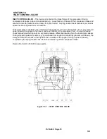
Inlet Control Valve (Body) Inspection -
The valve does not require maintenance or lubrication. If air/oil
leaks develop across the valve disc during pressurized conditions (e.g., machine stopped), valve seals
should be inspected for wear and tear signs:
1. Be sure the unit is completely off and oil sump is depressurized. Disconnect, lockout and tagout
power supply to the compressor package.
2. Close (when provided) valve isolating compressor package from air system.
3. Identify (by position) each tube connected to the valve body and remove.
4. Remove four bolts (Item 13) securing valve body to compressor body and remove valve.
5. Inspect poppet seals (o-ring) (Item 6, 10) for wear and tear. Replace, if necessary.
6. Remove lock ring (Item 12) and pull out cover (Item 4).
7. Inspect seals (Items 9, 11) for wear and tear. Replace if necessary.
8. Reassemble inlet control valve in reverse order.
Summary of Contents for VS80A
Page 33: ...13 18 609 Page 32 4 7 300CGE546 04 Ref Drawing Page 2 of 4...
Page 34: ...13 18 609 Page 33 4 8 300CGE546 04 Ref Drawing Page 3 of 4...
Page 35: ...13 18 609 Page 34 4 9 300CGE546 04 Ref Drawing Page 4 of 4...
Page 37: ...13 18 609 Page 36 4 11 301CGE546 B Ref Drawing Page 2 of 4...
Page 38: ...13 18 609 Page 37 4 12 301CGE546 B Ref Drawing Page 3 of 4...
Page 39: ...13 18 609 Page 38 4 13 301CGE546 B Ref Drawing Page 4 of 4...
Page 41: ...13 18 609 Page 40 4 15 302CGE546 05 Ref Drawing Page 2 of 4...
Page 42: ...13 18 609 Page 41 4 16 302CGE546 05 Ref Drawing Page 3 of 4...
Page 43: ...13 18 609 Page 42 4 17 302CGE546 05 Ref Drawing Page 4 of 4...
Page 45: ...13 18 609 Page 44 4 19 303CGE546 B Ref Drawing Page 2 of 4...
Page 46: ...13 18 609 Page 45 4 20 303CGE546 B Ref Drawing Page 3 of 4...
Page 47: ...13 18 609 Page 46 4 21 303CGE546 B Ref Drawing Page 4 of 4...
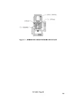
Page 70: ...13 18 609 Page 69 9 2 Figure 9 1 MINIMUM DISCHARGE PRESSURE CHECK VALVE...
Page 86: ...NOTES...
Page 87: ...NOTES...


