


13-8-621 Page 33
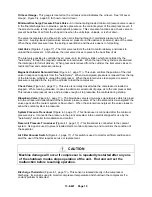
NOTICE
A sudden drop of zero pressure differential or sudden heavy oil carryover may
indicate a ruptured element.
Inspection
- After removal of separator element, shine a light inside the element to reveal areas of heavy
dirt or varnish deposits or breaks (ruptures) in element media.
Removal of Oil Separator For Inspection or Replacement
:
DANGER
Air/oil under pressure will cause severe personal injury or death. Shut down
compressor, relieve system of all pressure, disconnect, lockout and tagout
power supply to the starter before removing valves, caps, plugs, fittings, bolts
and filters.
DANGER
Compressor, air/oil reservoir, separation chamber and all piping and tubing
may be at high temperature during and after operation.
1. Be certain the unit is off and that no air pressure is in the oil reservoir. The compressor package will
automatically blowdown in about 2 minutes.
2. Close the air service valve located after the compressor package discharge.
3. Disconnect, lockout and tagout the power supply to the starter.
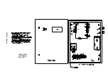
4. Remove the minimum pressure/check valve, see Item 1, Figure 5-6, page 34 (air/oil separator
housing) cover.
5. Lift out the air/oil separator element. See Item 2, Figure 5-6, page 34.
6. Inspect and/or replace the separator as necessary.
7. Clean the sealing surfaces on the air/oil separator and the minimum pressure/check valve.
8. Clean the orifice, Item 3, Figure 5-6, page 34, in the oil return line, the strainer, Item 4, Figure 5-6,
page 34, in the oil return line, and if necessary, the air/oil separator housing.
9. Grease the O-Ring on the separator element and install the separator into the housing.
10. Replace the O-Ring, Item 5, Figure 5-6, page 34, between the minimum pressure/check valve and
the air/oil separator housing.
11. Replace the sealing kit in the minimum pressure/check valve. After the assembling of the valve,
leave about .08 inch gap between the nut, Item 6, Figure 5-6, page 34, and the cover of the valve.
See “Changing Minimum Pressure/Check Valve Seals,” Section 4, page 20.
Summary of Contents for INTEGRA EFC99A
Page 9: ...13 8 621 Page 2 Figure 1 2 COMPRESSOR ILLUSTRATION 302EFC797 A Ref Drawing...
Page 12: ...13 8 621 Page 5 DECALS 206EAQ077 212EAQ077 218EAQ077 211EAQ077 207EAQ077...
Page 13: ...13 8 621 Page 6 DECALS 216EAQ077 217EAQ077 222EAQ077 221EAQ077 208EAQ077...
Page 29: ...13 8 621 Page 22 4 3 WIRING DIAGRAM 300EFC546 B Ref Drawing Page 1 of 2...
Page 30: ...13 8 621 Page 23 300EFC546 B Ref Drawing Page 2 of 2...


