13–8–610 Page 11
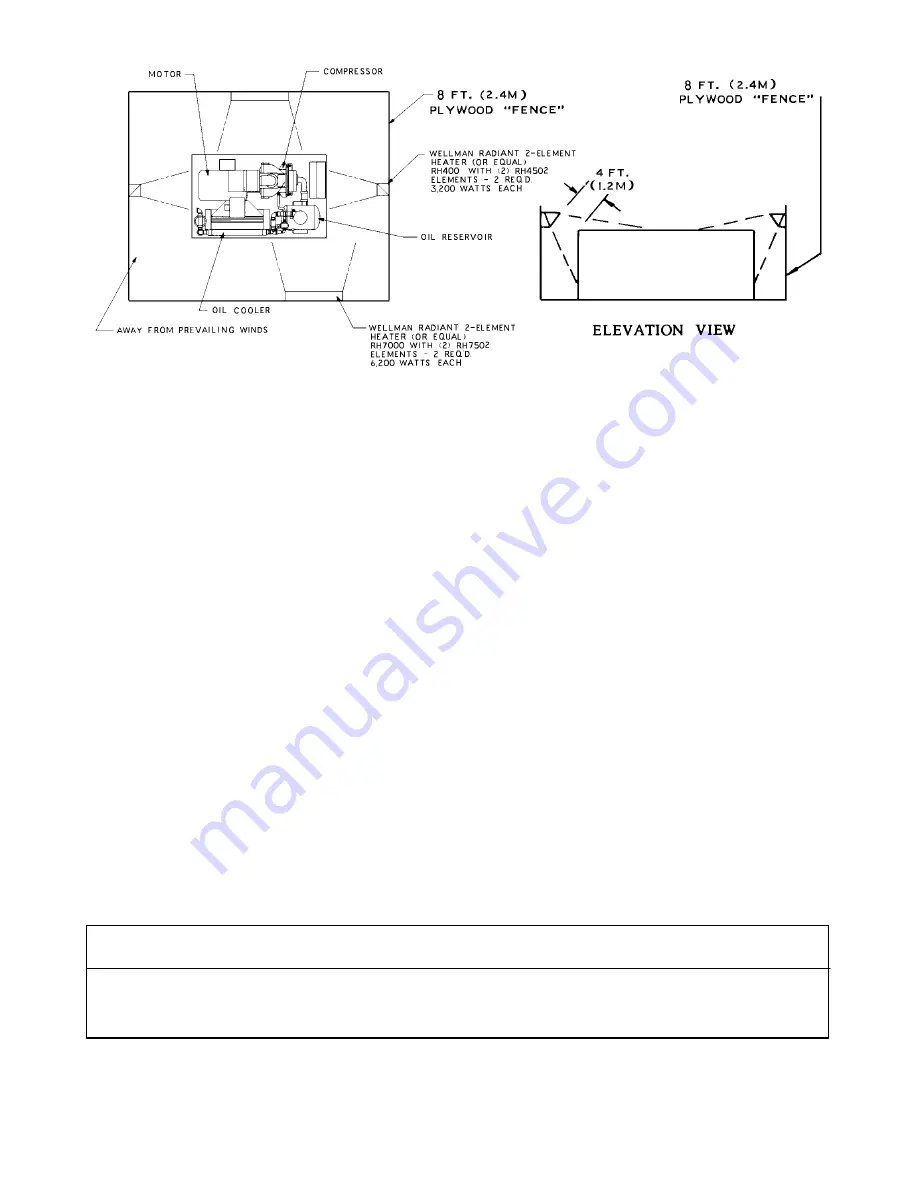
FIGURE 2–3 – COLD WEATHER INSTALLATION
Extreme Cold Weather Operation (Down To –40
_
F,
–40
_
C)
In addition to the above, the following should be pro-
vided:
1.
It will be necessary to provide shutters or to block
off part of the cooler in some manner since the
cooler is greatly oversized for operation in these
low temperatures. Since shutters are not pro-
vided as a factory option, blocking off a portion of
the cooler with plywood should be satisfactory.
2.
In extreme environments, run the unit in “Constant
Speed” only.
3.
Some means of providing heat during shutdown
should be provided. There are various methods
to accomplish this, but since openings are not pro-
vided for sump heaters, the use of radiant heaters
is recommended. The heaters should be sized to
provide at least a +10
_
F (–12
_
C) environment for
coolers, motor and sump. Figure 2–3, page 11,
shows how these might be located in a typical
installation and sizes required.
Remember unsheltered (outside) installations should
be avoided where possible. Installation next to a
heated building where enough heat can be used to
keep the compressor room above freezing will save
many complications in the operation and installation of
the unit.
Refer to Engineering Data Sheet 13–9–411, available
from an authorized Gardner Denver distributor, for the
advantages of using the heat recovered from rotary
compressors. This heat recovery could easily pay for
an adequate shelter for the unit.
AUXILIARY AIR RECEIVER – An auxiliary air receiver
is not required if the piping system is large and provides
sufficient storage capacity to prevent rapid cycling.
When used, an air receiver should be of adequate size,
provided with a relief valve of proper setting, a pressure
gauge and a means of draining condensate.
MOISTURE SEPARATOR/TRAP – Since the unit is
equipped with a built–in aftercooler, a combination
moisture separator and trap is furnished with the unit.
A means of draining condensate will need to be pro-
vided for.
Length of Inlet Line
Diameter of Pipe Size
0 to 10 Feet (0 to 3 Meters)
Same as Compressor Inlet Opening
. . . . . . . . . . . . . . . . . . . . . . . . . . . . . . . . . . . .
10 to 17 Feet (3 to 5 Meters)
One Size Larger Than Inlet Opening
. . . . . . . . . . . . . . . . . . . . . . . . . . . . . . . . . . .
17 to 38 Feet (5 to 11.5 Meters)
Two Sizes Larger Than Inlet Opening
. . . . . . . . . . . . . . . . . . . . . . . . . . . . . . . .
FIGURE 2–4 – INLET LINE LENGTHS
Summary of Contents for ELECTRA-SCREW EDEQHH
Page 11: ...13 8 610 Page 3 200EDE797 Ref Drawing FIGURE 1 3 PACKAGE OIL LEVEL GAUGE SEPARATOR AIR FILTER...
Page 12: ...13 8 610 Page 4 202EDE797 Ref Drawing FIGURE 1 4 PACKAGE CONTROLLER STARTER BOX...
Page 15: ...13 8 610 Page 7 DECALS 206EAQ077 212EAQ077 218EAQ077 211EAQ077 207EAQ077...
Page 16: ...13 8 610 Page 8 DECALS 216EAQ077 217EAQ077 222EAQ077 221EAQ077 208EAQ077...
Page 33: ...13 8 610 Page 25 FIGURE 4 10 WIRING DIAGRAM FULL VOLTAGE DUAL CONTROL 204EDE546 Ref Drawing...
Page 34: ...13 8 610 Page 26 FIGURE 4 11 WIRING DIAGRAM WYE DELTA 205EDE546 Ref Drawing...
Page 53: ......


