3. Safety Devices
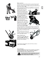
Switch block
Your machine is equipped with
a device
that when
deactivated, stops the switch
from being pressed thus
preventing accidental start-up.
Chain brake action on
switch release
Your machine is equipped with a device that blocks
the chain immediately as soon as the switch is
released; If this device should not work at any time,
the machine must NOT be used and must be taken
to an Authorised Service Centre.
Front hand guard / Chain brake lever
The front hand guard
is designed to prevent your
left hand from coming into contact with the chain (on
condition that the machine is held correctly
according to instructions). The front hand guard
also acts as a chain brake,
including a device that stops
the chain in less than 0.15
of a second in the case of
kickback. The chain brake
is released when the front
hand guard is pulled
backwards and clicked in
position
. The chain
brake is activated when the
front hand guard is pushed forward and the chain is
stopped
. The chain brake can be activated using
the left wrist by pushing forwards, or when the wrist
comes into contact with the front hand guard as a
result of kickback.
When the machine is used
with the bar in horizontal
position, for example
during tree felling, the
chain brake offers less
protection .
N.B.: When the chain
brake is activated, a safety
switch cuts off all current to
the motor.
Releasing the chain brake whilst the switch
is held will start the product.
Chain catcher
This machine is equipped
with a chain catcher
located under the sprocket.
This mechanism is
designed to stop the
backward chain movement
in the case of chain
breaking or derailing.
These situations can be
avoided by ensuring correct chain tension
(See Section 4. Assembly).
Rear hand guard
This acts to protect
the hand in the case of chain
breaking or derailing.
7
6
5
4
3
2
1
1
2
3
4
5
6
7
4. Assembly
1. Check the battery is not assembled on the product.
If it is, remove it.
2. Check that the chain brake is activated
.
3. Flip out the bar retaining inner knob
and rotate in an
anti-clockwise direction
to remove the drive sprocket cover.
10
9
8
BAR AND CHAIN ASSEMBLY
Take great care when assembling to ensure this is performed
correctly.
Wear Gloves.
GB
20
8
9
10


