background image

TRENCHER  


                                  TZ S  

Use and maintenance instructions – Spare parts                                                                                                                                                          Via L.da Vinci,32/B 

Rev. 01.2013 - EN (translation of the original instructions)


13


36034 Malo (VI) Italy


T E Z A


2.4- RESERVED RIGHTS  


The Manufacturer reserves all rights to this "Installation, use and maintenance instructions" manual. All 

the information contained herein (text, drawings, diagrams, etc.) is confidential. 

No part of this manual may be reproduced and disclosed (totally or partially) in any way (photocopies, 

microfilms  and  the  like)  without  the  written  authorisation  of  the  Manufacturer.  All  the  trademarks 

mentioned belong to their respective owners. 


3- TECHNICAL DESCRIPTION


3.1- NAME OF MACHINE 

The machine is called: 


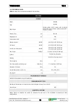
MANUAL TRENCHER        TZ S  


3.2- OPTIONAL EQUIPMENT 

The  machine  is  supplied  with  the  equipment  requested  by  the  Customer  already  mounted  on  its  jib 

support. To replace or change the equipment contact the Manufacturer or authorised dealer which will 

send specialised technicians to ensure these operations are performed correctly. 

The following equipment can be installed on the machine: 

• Trench jib - depth 45 cm - 32 pitches 


THIS  EQUIPMENT  MAY  ONLY  BE  MOUNTED  BY  THE  MANUFACTURER  OR  AUTHORISED  DEALER'S 
TECHNICIANS 


Summary of Contents for TZ S

Page 1: ...slation of the original instructions 1 36034 Malo VI Italy T E Z A USE AND MAINTENANCE INSTRUCTIONS SPARE PARTS CATALOGUE TZ S CHASSIS NUMBER YEAR OF CONSTRUCTION GARBIN GROUP SRL unipersonale Via L d...

Page 2: ...TURER DOCUMENT PAGE METHOD DECLARATION OF DELIVERY OF DOCUMENTATION Fill in all sections and sign Send a copy within 8 days from the date of delivery of the machine TESTING AND COMMISSIONING CERTIFICA...

Page 3: ...EMPLOYEES DO NOT ENTER THE MACHINE COMMISSIONING AREA FOR ANY REASON UNTIL FINAL TESTING HAS BEEN COMPLETED TESTING AND COMMISSIONING CERTIFICATE Performed by Manufacturer Authorised Dealer Date MACH...

Page 4: ...________________ Address ________________________________________________________ ________________________________________________________ ________________________________________________________ ____...

Page 5: ...s or if it has not been sufficiently or correctly serviced g Any faults must be notified in writing within 8 days from delivery failure to do so will invalidate the Purchasers rights as per this warra...

Page 6: ...viations page 12 2 4 Reserved rights page 13 3 TECHNICAL DESCRIPTION page 13 3 1 Name of machine page 13 3 2 Optional equipment page 13 3 3 Identification of components page 14 3 4 Dimensions page 17...

Page 7: ...age 36 7 9 Cleaning the machine page 37 7 10 Emergency stopping page 37 7 11 Starting after an emergency stop page 37 7 12 Prolonged disuse of the machine page 37 7 13 Starting the machine after prolo...

Page 8: ...ements of the following laws Directive 2006 42 EC and subsequent amendments and additions machinery Directive 2000 14 CE and subsequent amendments and additions implemented in Italy by Legislative Dec...

Page 9: ...cated in the CE declaration of conformity It consists of an aluminum plate printed in black with the following dimensions L 120 mm H 60 mm thickness 0 80 mm FIG 1 and is applied with four rivets to th...

Page 10: ...structions manual and strictly follow the relative instructions in order to guarantee their own safety and that of other people optimise performance of the machine and maximise the efficiency and life...

Page 11: ...aged 18 or over is professionally trained according to legislation in force in the country of use and is only authorised to turn on use adjust with the guards enabled and the machine off and turn off...

Page 12: ...mer possessing the professional and technical skills required by current occupational health and safety legislation MANUFACTURER S TECHNICIAN This person is a qualified technician provided by the manu...

Page 13: ...e without the written authorisation of the Manufacturer All the trademarks mentioned belong to their respective owners 3 TECHNICAL DESCRIPTION 3 1 NAME OF MACHINE The machine is called MANUAL TRENCHER...

Page 14: ...how and identify the main machine components KEY 1 Safety device for stopping engine red normally open operation 2 Adjustable lever for securing the handlebar 3 Front wheel 4 RH wheel 5 Trench jib sup...

Page 15: ...2013 EN translation of the original instructions 15 36034 Malo VI Italy T E Z A FIG 3 Identification of components KEY 15 Accelerator 16 Tow ratchet engage disengage leverr 17 Safety guard 18 Chain gu...

Page 16: ...L da Vinci 32 B Rev 01 2013 EN translation of the original instructions 16 36034 Malo VI Italy T E Z A FIG 4 Identification of components LH SIDE REAR FRONT MATERIAL DISCHARGE SIDE RH SIDE TRENCHING...

Page 17: ...nci 32 B Rev 01 2013 EN translation of the original instructions 17 36034 Malo VI Italy T E Z A FIG 5 Dimensions of machine with tool 3 4 DIMENSIONS FIG 5 shows the overall dimensions of the machine a...

Page 18: ...0 rpm 3 7 kW 5 0 HP 3600 rpm Max torque Nm kgf 12 4 Nm 12 6 kgf 2500 rpm Ignition Contact free transistor Starting Pull start with spring rewind Tank capacity litres 3 1 Fuel consumption at rated powe...

Page 19: ...with 45 cm trench jib and fuel tank full 133 kg For dimensions see FIG 5 PERFORMANCE Trench depth standard 45 cm Trench width Slots 11 13 cm Needles 10 12 cm Mixed 11 13 cm SAFETY DEVICES Safety bar...

Page 20: ...and compliant with the occupational health and safety legislation in force in the country of use The machine must be placed on a flat floor or ground with no irregularities or obstacles large stones t...

Page 21: ...OL 3 1 litres TAB 6 Products used 3 8 POWER SOURCES 3 9 PROCESSING PHASES 1 Checks prior to starting see para 7 3 2 Correct posture see para 7 4 3 Starting the machine see para 7 5 4 Handling the mach...

Page 22: ...Y FORBIDDEN TO TRANSPORT PEOPLE ANIMALS OR OBJECTS ON THE MACHINE IT IS STRICTLY FORBIDDEN TO MOVE AND USE THE MACHINE ON SLOPING AND UNSTABLE TERRAIN 5 MAX PERMITTED SIDEWAY AND FORWARD SLOPE IT IS S...

Page 23: ...ORT TO LOAD AND UNLOAD THE MACHINE SUITABLE CERTIFIED RAMPS MUST BE USED APPROPRIATELY SECURED TO THE VEHICLE WITH A MAX INCLINATION OF 30 AFTER LOADING THE MACHINE IT MUST BE SECURED TO THE FLOOR OF...

Page 24: ...iples EN 294 1992 Safety distances to prevent danger zones being reached by the upper limbs EN 349 1994 Safety of machinery Minimum gaps to avoid crushing of parts of the human body TAB 7 Reference Di...

Page 25: ...BY THE MANUFACTURER REPLACE DETERIORATED SAFETY AND INDICATOR SIGNS REQUESTING REPLACEMENTS FROM THE MANUFACTURER 6 2 SAFETY SYSTEMS The following safety systems are used in the machine 1 GUARDS These...

Page 26: ...ct with the moving equipment DANGER FLYING OBJECTS When the machine is operating there is the danger of the moving equipment accidentally projecting objects earth stones etc PROHIBITIONS IT IS FORBIDD...

Page 27: ...tract from the dust generated by the excavated material e g earth dust Eye protection Safety goggles When digging protects the eyes from material projected by the equipment Hearing protection Ear muf...

Page 28: ...s injury normally irreversible MEASURES ADOPTED Requirement to use personal protective equipment PPE see para 6 4 Requirement to occupy the positions indicated in para 7 1 Safety signs see para 6 3 Re...

Page 29: ...e the work procedures indicated in this manual TAB 13 Residual risk N 4 The term RESIDUAL RISKS is used to identify all the cases that can cause injury and or death and that are difficult to indicate...

Page 30: ...AL OPERATIONS DESCRIBED IN THE RELATIVE PARAGRAPHS POSITIONS OCCUPIED WITH THE MACHINE OPERATING FIG 7 A Positions occupied by authorised operators POSITIONS OCCUPIED WITH THE MACHINE TURNED OFF FIG 7...

Page 31: ...chine in an emergency using the engine stop safety device red lever 3 Drive and move the machine using the control levers 4 Visually control the trench Standing on the LH side of the machine to 1 Visu...

Page 32: ...N translation of the original instructions 32 36034 Malo VI Italy T E Z A FIG 8 Command and control levers 7 2 COMMAND AND CONTROL LEVERS From the driving position A see para 7 1 the authorised operat...

Page 33: ...lerates the engine 16 Tow ratchet ENGAGE DISENGAGE lever Forwards the tow ratchet does NOT drive the cog Back the tow ratchet drives the cog BEFORE STARTING THE MACHINE AUTHORISED OPERATORS MUST PERFO...

Page 34: ...perating posture WHILE OPERATING THE MACHINE THE CORRECT POSTURE MUST BE USED SEE PARA 7 4 7 4 CORRECT OPERATING POSTURE The authorised operator must use the correct operating posture indicated in FIG...

Page 35: ...NCLINATION GREATER THAN 5 AND A LONGITUDINAL INCLINATION GREATER THAN 5 SEE PARA 3 11 WHILE OPERATING THE MACHINE THE CORRECT POSTURE MUST BE USED SEE PARA 7 4 MACHINE STATUS Off as described in para...

Page 36: ...pos 9 taking care to avoid any projected material 5 After resuming the correct operating posture see para 7 4 move the machine along the trench see fig 9 engaging the tow ratchet with the lever see fi...

Page 37: ...AFTER AN EMERGENCY STOP Only after eliminating the cause s of the emergency carefully ensuring they have not caused damage and or faults to the machine and obtaining the permission of the Safety Manag...

Page 38: ...NCHER TZ S Use and maintenance instructions Spare parts Via L da Vinci 32 B Rev 01 2013 EN translation of the original instructions 38 36034 Malo VI Italy T E Z A 7 14 WIRING DIAGRAM COIL SPARK PLUG S...

Page 39: ...EQUENCY WORK POINT TYPE OF OPERATION EVERY DAY Cable and Red lever Safety device for stopping the engine Visual inspection of operating status Engine Maintenance Sheet N 01 Check the oil level and if...

Page 40: ...jib gear reducer Maintenance Sheet N 08 Check the oil level and if necessary top up with AGIP ROTRA MP SAE 80W 90 oil or similar Check the chain toolholder and screw for wear Maintenance Sheet N 09 Vi...

Page 41: ...ove the oil filling cap level stick of the oil and clean the stick 2 Fit the oil filling cap level stick into the filler but do not tighten remove it to check the oil level 3 If the oil level is near...

Page 42: ...trol Topped up with litres Level control Topped up with litres Level control Topped up with litres Level control Topped up with litres Level control Topped up with litres Level control Topped up with...

Page 43: ...inal instructions 43 36034 Malo VI Italy T E Z A MAINTENANCE SHEET N 02 WORK POINT MAIN SHAFT BEARINGS TYPE OF OPERATION GREASING EVERY DAY 1 Grease the main shaft bearings using the grease nipple Pos...

Page 44: ...inci 32 B Rev 01 2013 EN translation of the original instructions 44 36034 Malo VI Italy T E Z A MAINTENANCE SHEET N 02 WORK POINT MAIN SHAFT BEARINGS TYPE OF OPERATION GREASING DATE REMARKS SIGNATURE...

Page 45: ...arts Via L da Vinci 32 B Rev 01 2013 EN translation of the original instructions 45 36034 Malo VI Italy T E Z A MAINTENANCE SHEET N 03 WORK POINT ENGINE AIR FILTER TYPE OF OPERATION CLEAN BOX AND FILT...

Page 46: ...32 B Rev 01 2013 EN translation of the original instructions 46 36034 Malo VI Italy T E Z A MAINTENANCE SHEET N 03 WORK POINT ENGINE AIR FILTER TYPE OF OPERATION CLEAN BOX AND FILTER DATE REMARKS SIGN...

Page 47: ...E Z A MAINTENANCE SHEET N 04 WORK POINT TOOLS AND SEATS TYPE OF OPERATION VISUAL INSPECTION FOR WEAR AND LUBRICATION EVERY DAY 1 Check the tools Ref 1 and seats Ref 2 for wear 2 If necessary replace t...

Page 48: ...1 2013 EN translation of the original instructions 48 36034 Malo VI Italy T E Z A MAINTENANCE SHEET N 04 WORK POINT TOOLS AND SEATS TYPE OF OPERATION VISUAL INSPECTION FOR WEAR AND LUBRICATION DATE RE...

Page 49: ...EN translation of the original instructions 49 36034 Malo VI Italy T E Z A MAINTENANCE SHEET N 05 WORK POINT NUTS AND BOLTS ON THE WHOLE MACHINE TYPE OF OPERATION CHECK AND IF NECESSARY TIGHTEN THE N...

Page 50: ...slation of the original instructions 50 36034 Malo VI Italy T E Z A MAINTENANCE SHEET N 05 WORK POINT NUTS AND BOLTS ON THE WHOLE MACHINE TYPE OF OPERATION CHECK AND IF NECESSARY TIGHTEN THE NUTS AND...

Page 51: ...3 cm 3 If the chain is too tight proceed as follows a Loosen the nut Ref 1 by a few turns b Loosen the screws Ref 2 until the required chain tightness is achieved c Fully tighten the nut Ref 1 4 If t...

Page 52: ...GHTEN THE CHAIN LUBRICATION DATE X REMARKS OPERATOR SIGNATURE Voltage control Lubrication Voltage control Lubrication Voltage control Lubrication Voltage control Lubrication Voltage control Lubricatio...

Page 53: ...EN translation of the original instructions 53 36034 Malo VI Italy T E Z A MAINTENANCE SHEET N 07 WORK POINT OPEN GREASE NIPPLES LUBRICATE TYPE OF OPERATION GREASE LUBRICATE EVERY DAY 1 Grease all the...

Page 54: ...Rev 01 2013 EN translation of the original instructions 54 36034 Malo VI Italy T E Z A MAINTENANCE SHEET N 07 WORK POINT OPEN GREASE NIPPLES LUBRICATE TYPE OF OPERATION GREASE LUBRICATE DATE REMARKS...

Page 55: ...034 Malo VI Italy T E Z A MAINTENANCE SHEET N 08 WORK POINT TRENCH JIB GEAR MOTOR TYPE OF OPERATION CHECKING THE OIL LEVEL AFTER THE FIRST 50 HOURS OF WORK OPERATION TO PERFORM WHEN THE OIL IS COLD 1...

Page 56: ...vel control Topped up with litres Level control Topped up with litres Level control Topped up with litres Level control Topped up with litres Level control Topped up with litres Level control Topped u...

Page 57: ...N TOOLHOLDER AND SCREW FOR WEAR TYPE OF OPERATION VISUAL INSPECTION FOR WEAR AND LUBRICATION AFTER THE FIRST 50 HOURS OF WORK 1 Check the tools Ref 1 and seats Ref 2 for wear 2 If necessary replace th...

Page 58: ...UAL INSPECTION FOR WEAR AND LUBRICATION DATE X REMARKS OPERATOR SIGNATURE Check for wear Lubrication Check for wear Lubrication Check for wear Lubrication Check for wear Lubrication Check for wear Lub...

Page 59: ...INT CHECK THE TRANSMISSION BELT CHAIN TYPE OF OPERATION VISUAL INSPECTION FOR WEAR AND TIGHTNESS AFTER THE FIRST 50 HOURS OF WORK 1 Remove the LH safety guard pos 1 see Fig 3 pos 15 2 Check the belts...

Page 60: ...IGHTNESS DATE X REMARKS OPERATOR SIGNATURE Check for wear Voltage control Check for wear Voltage control Check for wear Voltage control Check for wear Voltage control Check for wear Voltage control Ch...

Page 61: ...CHANGING THE OIL AFTER THE FIRST 50 HOURS OF WORK AND THEN AFTER EVERY 100 HOURS 1 Heat the engine for a few moments to allow the engine oil to drain more easily 2 CONSULT THE ATTACHED HONDA ENGINE M...

Page 62: ...a Vinci 32 B Rev 01 2013 EN translation of the original instructions 62 36034 Malo VI Italy T E Z A MAINTENANCE SHEET N 11 WORK POINT MOTOR TYPE OF OPERATION CHANGING THE OIL DATE REMARKS SIGNATURE N...

Page 63: ...G THE OIL AFTER THE FIRST 100 HOURS OF WORK AND THEN AFTER EVERY 100 HOURS 1 Place a suitable oil collector bin under the drain cap 2 Remove the oil vent cap Ref 1 3 Remove the drain cap Ref 2 and dra...

Page 64: ...2 B Rev 01 2013 EN translation of the original instructions 64 36034 Malo VI Italy T E Z A MAINTENANCE SHEET N 12 WORK POINT TRENCH JIB GEAR REDUCER TYPE OF OPERATION CHANGING THE OIL DATE REMARKS SIG...

Page 65: ...nal instructions 65 36034 Malo VI Italy T E Z A MAINTENANCE SHEET N 13 WORK POINT WHEELS TYPE OF OPERATION CHECK TYRE PRESSURE AND WEAR AFTER THE FIRST 100 HOURS OF WORK AND THEN AFTER EVERY 100 HOURS...

Page 66: ...32 B Rev 01 2013 EN translation of the original instructions 66 36034 Malo VI Italy T E Z A MAINTENANCE SHEET N 13 WORK POINT WHEELS TYPE OF OPERATION CHECK TYRE PRESSURE AND WEAR DATE REMARKS SIGNAT...

Page 67: ...LATION IN FORCE IN THE COUNTRY OF USE OF THE MACHINE ALL THE COMPONENTS OF THE MACHINE MUST BE IDENTIFIED ACCORDING TO THE EWC CODES EUROPEAN WASTE CATALOGUE AND DISPOSED OF BY AUTHORISED SPECIALISED...

Page 68: ...es in order to safely lift and transport the machine or equipment using the hand signals indicated in European Directive 92 58 EEC see para 10 2 wearing the personal protective equipment indicated in...

Page 69: ...the palm facing inwards and slowly makes a circle VERTICAL DISTANCE The hands indicate the relevant distance C HORIZONTAL MOVEMENTS MOVE FORWARDS Both arms are bent with the palms facing upwards and...

Page 70: ...ORDERING INDEX TO SPARE PARTS TABLES 1 Identify the N of the spare part to order in the relative SPARE PARTS TABLE see following pages 2 Photocopy the relative SPARE PARTS ORDER CONFIRMATION SHEET an...

Reviews: