background image

ITC Series 

ITC6500 Series Installation Guide 

CBC AMERICAS CORP. - EAST COAST +1 (919) 230-8700 | WEST COAST +1 (310) 222-8600 | 52 (55) 5280-4660                                

ganzsecurity.com. 01/17 

4. INSTALLATION 

4.1. Installing Cable Gland  


1) 

 Detach the back cover by twisting it counter-clockwise. 

2)

 Disassemble the provided cable gland unit. There will be an electrical nut, a rubber sealing 

ring inserted inside the cable gland, a gland body, and a sealing nut. 

3)

 Pass the electrical nut through the ends of the necessary cables. 

4)

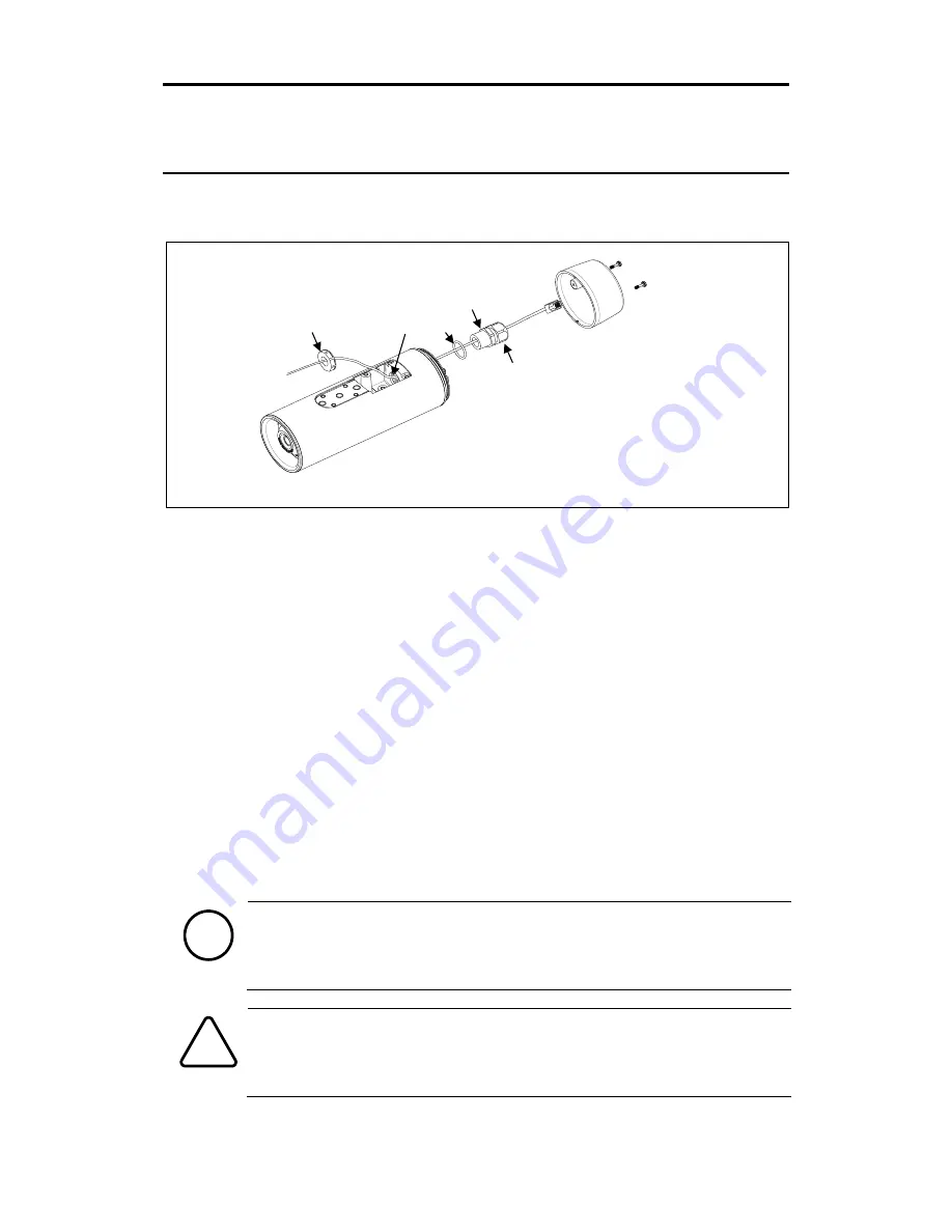
 Pass the cables through the holes both on the back and the bottom of the camera by referring 

to the image above. 

5)

  Pass  the  provided  O-ring  and  gland  body  through  the  ends  of  the  cables  that  are  on  the 

backside of the camera.  

6)

  Insert the cables into the rubber sealing ring at the point where about 4.5 inches (11.5 cm) 

of the cable ends remains to connect to the corresponding connectors on the back panel later. 

7)

 Push the rubber sealing ring through the claw of the gland body. 

8)

 Insert the sealing nut into the thread of the gland body, and tighten it by turning the nut on 

the thread. The rubber sealing ring will be tightened to fill the gap between the rubber sealing 
ring and the cables. 

9)

 Push the gland unit through the hole on the back of the camera so that the other end of the 

thread on the gland unit will be inserted into the hole for gland near the bottom of the camera 
body. 

10)

 Fix the gland unit to the hole by inserting the electrical nut and tightening it on the thread 

of the gland unit. 


When you insert a video out cable together with other cables such as RJ45, DIDO, 
and audio cables, a thin type of the BNC cable is recommended as the standard 
BNC cable is too thick to be inserted together with the other cables into the rubber 
sealing ring. 


Use the detachable cable with a separate BNC connector to pass the hole of the 
sealing nut. Otherwise, use the female type head of the BNC cable to pass the hole 
of the sealing nut. 

Note

i

Caution

!

Hole for gland 

Electrical nut 

O-ring 

Gland body 

Sealing nut 

Summary of Contents for ZNT1-H Series

Page 1: ...ZNT1 H Series Installation Manual...

Page 2: ...it Please do not install the camera in a place exposed to direct sunlight Do not operate the camera in environments beyond the specified temperature Refer to Environment Condition on APPENDIX A SPECIF...

Page 3: ...Installing the Sunshield 11 4 6 Adjusting Image Focus 11 4 7 Installing with Bracket 12 5 CONNECTIONS 13 6 CONFIGURATION 16 6 1 Set up network environment 16 6 1 1 Generic IP Environment 16 6 1 2 Cus...

Page 4: ...tallation Guide CBC AMERICAS CORP EAST COAST 1 919 230 8700 WEST COAST 1 310 222 8600 MEXICO 52 55 5280 4660 ganzsecurity com 01 17 4 APPENDIX D DIMENSIONS 26 APPENDIX E HEXADECIMAL DECIMAL CONVERSION...

Page 5: ...d MJPEG Motion JPEG Max 9 fps or 30 fps in all available resolutions depending on the camera model Text Overlay Video Motion Detection supported Audio Two way audio streaming Audio compression G 711 L...

Page 6: ...ield DC Power Jack Cable Tamper Resistant Screws x 8 Base Mount Terminal Blocks Stem Bumpers x 2 and 1 Spare Cable Gland Electrical Nut O ring Silica Gel Packet Quick Start Guide Quick Installation Gu...

Page 7: ...camera to the factory default settings Refer to 6 3 Reboot and 6 4 Factory Default for the pressing duration and more information Terminal Connectors for DI DO Connecting terminal blocks for digital...

Page 8: ...de CBC AMERICAS CORP EAST COAST 1 919 230 8700 WEST COAST 1 310 222 8600 MEXICO 52 55 5280 4660 ganzsecurity com 01 17 8 Terminal Connector for Power Adaptor Connect terminal blocks for power supply R...

Page 9: ...er 7 Push the rubber sealing ring through the claw of the gland body 8 Insert the sealing nut into the thread of the gland body and tighten it by turning the nut on the thread The rubber sealing ring...

Page 10: ...o the corresponding connectors on the back panel of the camera body Refer to 5 CONNECTIONS for more information about each connector 4 3 Installing Base Mount 1 Insert the provided 8 tamper resistant...

Page 11: ...ield 1 Insert the two provided stem bumpers to the holes at the bottom of the sunshield 2 Place the sunshield on top of the camera body and snap the sunshield to the base mount 4 6 Adjusting Image Foc...

Page 12: ...ies to mount this camera are as follows Model Names Combinations WB 1W Wall Mount Bracket JB 1W Ceiling Mount Bracket PMA2 Pole Mount Adaptor WB 1W PMA2 Refer to the corresponding accessory model s in...

Page 13: ...f each is respectively normally open N O and normally closed N C so that you can opt to use one accordingly Only the relay type is supported Digital Output 1 Relay Rating Max 30VDC 1A Normally Open N...

Page 14: ...m Max 50mA Relay Rating Max 30VDC 1A Do not exceed the maximum input voltage or relay rate Audio Connection The camera provides a mono audio input and output Due to low audio output power an amplified...

Page 15: ...r Ethernet for more information To operate your camera by using 12VDC make sure the polarity is correct before connecting the power cable Incorrect connection may cause damage to the device RJ45 Conne...

Page 16: ...ent In case of generic private network environment where IP address 192 168 XXX XXX are used users may view the live streaming images on a web page using the device s default IP address 1 Convert the...

Page 17: ...fy the device s default IP address for customized network area 1 Find the device from the IPAdminTool s list and highlight the device s name 2 Right click the mouse and select IP Address IP Setup wind...

Page 18: ...gh a web browser The default username and password is root pass 6 2 1 ActiveX Installation 1 When the browser asks to install the AxUMF software click Install to proceed 2 When Setup installation pop...

Page 19: ...shows the product name IP address MAC address and etc 1 From the IPAdminTool s product list select the device by highlighting it 2 Right click the mouse and select Web view Then the system s default w...

Page 20: ...4 Factory Default Resetting the device back to the factory default will initialize all parameters including the IP address back to the factory defaults On the Device 1 Press the reset button for 10 s...

Page 21: ...certain times in the middle of system booting The firmware files required for system booting are damaged There are conflicts in the system settings How to recover your system from Safe Mode The messag...

Page 22: ...ain High profile MPEG 4 Part 10 AVC MJPEG Motion JPEG Number of Streams Dual Stream Configurable Resolution ZNT1 HET14G ZNT1 HBT14G 320x240 QVGA 160x120 QQVGA ZNT1 HAT24G ZNT1 HBT24G 640x480 VGA 320x2...

Page 23: ...V PoE IEEE802 3af Class 0 Power Consumption Max 10W 12VDC Audio Input MIC in Max2Vp p 20K 90dB Audio Output Line out 60mW 16 95dB D I Max 50mA 5VDC TTL level 1 5V threshold D O 1 D O 2 Max 1A 30VDC En...

Page 24: ...Object Identification Recognition VCA Event Detection 9 Person 220 285 340 1 450 Vehicle 560 725 770 3 390 24 Person 75 100 130 555 Vehicle 205 265 300 1 375 42 Person 45 60 70 330 Vehicle 120 160 17...

Page 25: ...E standard allows up to 25 5 W Max 34 2 W of power the device PoE has advantages over conventional power in such places where AC powers cannot be reached or is expensive to wire Power Comparison Prope...

Page 26: ...ITC Series ITC6500 Series Installation Guide CBC AMERICAS CORP EAST COAST 1 919 230 8700 WEST COAST 1 310 222 8600 MEXICO 52 55 5280 4660 ganzsecurity com 01 17 26 APPENDIX D DIMENSIONS Unit mm...

Page 27: ...A0 160 C5 197 EA 234 0D 13 32 50 57 87 7C 124 A1 161 C6 198 EB 235 0E 14 33 51 58 88 7D 125 A2 162 C7 199 EC 236 0F 15 34 52 59 89 7E 126 A3 163 C8 200 ED 237 10 16 35 53 5A 90 7F 127 A4 164 C9 201 E...

Page 28: ...5 5280 4660 ganzsecurity com 01 17 28 REVISION HISTORY MAN DATE M D Y Comments 05 2016 A 05 02 2016 First release version 08 2016 A 08 11 2016 Added 4 6 Adjusting Image Focus 10 2016 A 10 13 2016 Adde...

Reviews: