background image

Use the joystick or pan keys to select any preset number, Group tour No. 
I-4. ALARM SET - AUX ACT 
You can select one of BLK (No AUX triggering) / AUX1 (triggering AUX1) / AUX2 (triggering AUX2) 
and default value is BLK. 
If ALARM triggers AUX, AUX will be off after 5 seconds. If many ALARMs trigger AUX port one by 
one, the last one will be off after 5 seconds. 
I-5. ALARM SET - SAVE 
After setting up the alarm features, to save the data move the joystick right or press the pan right 
key when the cursor is on SAVE. After saving the data, the cursor moves to Alarm NO.2 
automatically to prepare for the next alarm. 
I-6. ALARM SET - EXIT 
To escape this page, move the joystick right or press the pan right key. 

  Before activating Alarms, you must set ALARM ENABLE at DOME SET ALARM ENABLE. 
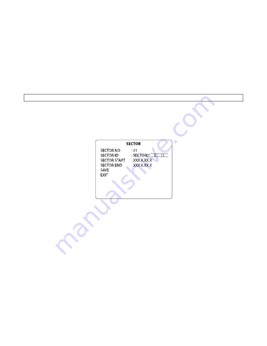
 

J. Sector Set 


Up to 8 programmable sectors are available with 16 characters. 
This feature is useful to memory the certain location such as parking zone or so on. 


J-1. SECTOR SET - SECTOR NO. 
Up to 8 programmable sectors are available. 
J-2. SECTOR SET - SECTOR ID 
To set a SECTOR ID, use the joystick or pan left /right keys. 
Press ZOOM TELE button to move to the next character from left to right and ZOOM WIDE button 
to move to the next character from right to left. (Space 
displays when 

  appears.) 

J-3. SECTOR SET - SECTOR START 
To set a SECTOR START position press FOCUS FAR button then move the joystick or pan keys 
to set the position. Press FOCUS FAR button again to escape. 
J-4. SECTOR SET - SECTOR END 
To set a SECTOR END position press FOCUS FAR button then move the joystick or pan keys to 
set the position. To press FOCUS FAR button again to escape. 
J-5. SECTOR SET - SAVE 
After setting the SECTOR position, to save the data move the joystick right or press the pan right 
key when the cursor is on SAVE. After saving the data, the cursor moves to sector No. 2 
automatically to prepare for the next sector. 
J-6. SECTOR SET 

  EXIT 

To escape this page, move joystick to the right or press the pan right key. 

Summary of Contents for ZC-PT336N-IR

Page 1: ...e World s First 360 Endless PAN TILT Motion Auto LED Brightness Control by Distance Range Auto LED Pulse Control by Distance Range PAN TILT Torque Compensation Step Out Prevention Contents CONTENTS 2...

Page 2: ...ICATION 43 DIMENSIONS 44 Components 1 IR CAMERA 1SET 2 MANUAL 1EA Warnings Cautions If you fail to read this information and handle the product incorrectly death or serious injury may occur The unit s...

Page 3: ...mes with a variety of options in order to offer a best fit solution for virtually any application Rated to an industry leading IP68 the vandal resistant aluminum camera housing is suitable for install...

Page 4: ...TORQUE COMPENSATION Pan Tilt Torque vibration sensor keeps the Pan Tilt Motor securely in place during strong winds AUTO LED PULSE CONTROL BY DISTANCE RANGE It automatically controls the pulse of LED...

Page 5: ...Part Names B Connection Method...

Page 6: ...ND VIRMILION ORANGE ALARM 1 VILOET ALARM 2 Explanation PINK ALARM 3 SKY BLUE ALARM 4 Color USE BLACK GND RED AC 24 BLUE RS 485 D WHITE AC 24 GREEN RS 485 D BLACK F G Installation A Ceiling Mount Brack...

Page 7: ...ket to the Camera with 4 pieces of M4X16 screws and spring washer FIG 2 A 3 Connect the Safety wire of the Camera to the Bracket In order to avoid getting entangled in the Camera fasten the Safety wir...

Page 8: ...PONENTS 1 POLE STAND 1EA 6 SCREW M4 x 16 5EA 2 BOLT M10 x 45 4EA 7 SPRING WAHGER 4 5EA 3 NUT M10 4EA 8 WRENCH 3mm 1EA 4 FLAT WASHER 4EA 9 MANUAL 5 SPRING WASHER 10 4EA B 1 When you install IR PTZ Came...

Page 9: ...and with pieces of M4 16 screws FIG 7 B 3 Connect the Safety Wire of the camera to the bracket In order to avoid getting entangled in the camera fasten the Safety wire to the bracket with Cable Tie FI...

Page 10: ...the wall make 4 holes at the edge with 13 in diameter and 37mm in depth and install 4 pieces of Anchor bolt in the 13 holes at the edge FIG 11 If you want to connect the cables from the inside of the...

Page 11: ...ed in the Camera fasten the Safety wire to the bracket with Cable tie FIG 13 C 4 When you want to connect the cables from the inside of wall pass the cables through the wall When you want to connect t...

Page 12: ...SET Auto Scan Executing Auto Scan 70 PRESET VIB CORR Selectable On Off in picture Stabilization Function 71 78 PRESET Group Tour Executing Group Tour 1 8 81 88 PRESET Pattern Executing Pattern 1 8 91...

Page 13: ...operation When you press 92 Preset button the image freezes but the camera is still working as operation such as tour pattern or auto scan To return to normal images press 92 Preset button again This...

Page 14: ...atically verifying TX Connection Test If Not Tested is displayed in the test The result which is not received any signal from DVR or controller Wrong connecting way such as the protocol baud rate or R...

Page 15: ...OSD Menu Setting To enter OSD Menu press the button 95 Preset then OSD Main Menu is displayed...

Page 16: ...is for Home Position basically including the Recover On ON it would be indicated the number Relevant function number is for time and Relevant function is that what operation product will be working on...

Page 17: ...DOME SET NEXT PAGE SYSTEM SET To enter system set use the joystick right to move when cursor on system set Flip status available and the default setting is NORMAL Move joystick right or left direction...

Page 18: ...001 255 on the password blank area and again on the confirm blank area Then CONFIRMED is displayed on the monitor and the menu will go back to the previous age automatically If you press an incorrect...

Page 19: ...Protocol and baud rate are shown due to the dip switch setting Firmware version and upgraded date will change if upgraded Camera module is setting as follows OSD Menu Setting B 7 6 DOME SET NEXT PAGE...

Page 20: ...light key to when the cursor is at LOAD OPTIMIZED DEFAULT to enter the next page Move joystick or the pan right key so that the cursor is over YES then press the FOCUS NEAR button ALL DATA INITIALIZIN...

Page 21: ...Full Auto Manual Auto Changed according to light level automatically Manual It can be changed into other one using the Focus Far Key of controller and on ON the DSS Digital Slow Shutter it should be s...

Page 22: ...94 Preset button C 8 CAMERA SET DSS MODE DIGITAL SLOW SHUTTER If digital slow shutter is enabled the exposure time of the camera is increased thus allowing more light to be collected and improving low...

Page 23: ...ing on D 5 FREEZE ALL You can set it up into ON OFF on ON Freeze all should be working on D 6 PRESET SAVE Move the joystick right or press the pan right key when the cursor is at SAVE and then the cur...

Page 24: ...Preset buttons launch group tours 1 8 F 1 TOUR SET TOUR NO Up to 8 group tours can be programmed F 2 TOUR SET TOUR TITLE To set a tour title use the joystick left right or pan left right keys Each tit...

Page 25: ...MOVE ADJUST To set the blocking area press FOCUS FAR button when MOVE MODE is displayed Then use the joystick or pan keys to the user defined area in order to set the blocking area Then press FOCUS FA...

Page 26: ...RN TITLE move Joystick left right or use the pan keys Press ZOOM TELE button moves to the next character from the left right and ZOOM WIDE button moves to the next character from the right left Space...

Page 27: ...Up to 4 alarms are selectable by using joystick right or pressing the pan right key when the cursor is on ALARM NO I 2 ALARM SET ALARM INPUT Alarm inputs can be programmed as NC Normally Close or NO N...

Page 28: ...he certain location such as parking zone or so on J 1 SECTOR SET SECTOR NO Up to 8 programmable sectors are available J 2 SECTOR SET SECTOR ID To set a SECTOR ID use the joystick or pan left right key...

Page 29: ...joystick to the right or left direction then this camera is ready to operate Dip Switch Setting A ID Setting The camera has camera ID to be controlled by controller or DVR After opening set ID using...

Page 30: ...Dip Switch Setting...

Page 31: ...Dip Switch Setting...

Page 32: ...Dip Switch Setting...

Page 33: ...Dip Switch Setting...

Page 34: ...Dip Switch Setting...

Page 35: ...Dip Switch Setting B 485 Termenation The 8th of DIP SW2 is used for 100 termination Set ON DIP SW2 1st of only the last looped camera from the controller...

Page 36: ...used Trouble Shooting If you have trouble setting up or operating the camera refer to the following Problem Solution NO OPERATION Check if the power supply is AC 24V Check if RS 485 communication cabl...

Page 37: ...Specification...

Page 38: ...Dimensions...

Page 39: ......

Reviews: