background image


14


INSTALLATION


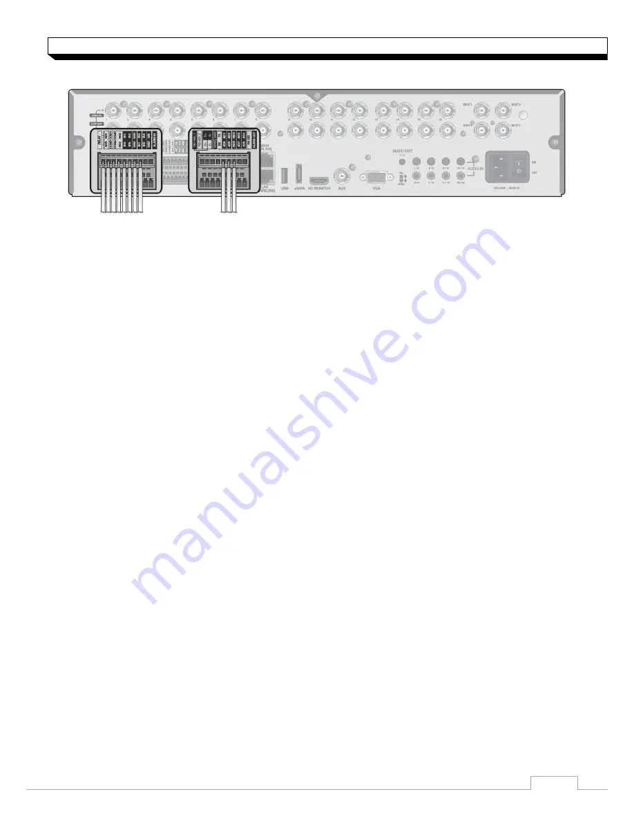
Alarm I/O Connection 


To connect the  Alarm  input  signal 

Connect  the  signal  line  of  an  alarm  input  device  such  as  sensor  to  rear 

[ALARM  IN]

  port 

1.  Loosen  screws  on 

[IN1]

  through 

[IN16]

  port  and 

[GND]

  port  of  the  provided  terminal 

block.   

2.  Insert  one  end  of  alarm  signal  cable  alarm  input  terminal  hole  below  the  screw  hole, 

and  then  fasten  the  screw. 

3.  Insert  ground  signal  wire  into  the  hole  of  the 

[GND]

  port  (shown  also  below  the   

screw),  and  tighten  the  screw. 

4.  To check  proper  insertion  of  the  cable,  gently  pull  the  cable  and  test  whether  it   

disconnects.  To disconnet  the  cable,  loosen  the  screw  and  pull  out  the  cable. 

To connect the  Relay/Alarm  output signal 

Connect  the  signal  line  of  an  alarm  output  to  rear 

[RELAY]

  port 

1.  Loosen  the  screws  on  the 

[NO]

  or 

[NC]

  port  and 

[COM]


port  of  the  provided   

terminal  bloack. 

2.  Insert  the  alarm  signal  wire  into  the  hole  of  the 

[NO]


or


[NC]

  input  prot  (shown   

below  the  screw),  and  tighten  the  screw. 
Check  the  relay  type  befere  selecting  a  proper 


NO  (Normal Open) : normally Open but switching to Close if an alarm out occurs. 


COM : Insert the grounding wire. 


NC  (Normal Close) : Normally Close but switching to Open if an alarm out occurs. 

3.  Insert the ground  signal  wire into  the  hole  of  the 

[COM]

 port  and  tighten  screw. 

 
  Or,  you  can  connect  the  signal  cable  of  the  alarm  output  device  to  the 

[ALARM  OUT]


1.  Loosen  screws  on 

[AO1]

  through 

[AO8]

  port  and 

[GND]

  port  of  the  terminal  block.   

2.  Insert  the  alarm  signal  wire  into  the  hole  of  the  AO  port  and  tighten  the  screw. 

3.  Insert  the  ground  signal  wire  into  the  hole  of  the 

[GND]

  port  and  tighten  the  screw.   

4.  To check  proper  insertion  of  the  cable,  gently  pull  the  cable  and  test  whether  it   

disconnects.  To disconnet  the  cable,  loosen  the  screw  and  pull  out  the  cable. 

5.  Install  the  wire-connected  terminal  block  in  the  rear  port. 


Summary of Contents for digimaster DR-16FX5

Page 1: ...1...

Page 2: ...CONTENT OVERVIEW 3 Before Installation 4 Key Features 6 Front Panel 7 Rear Panel 8 Remote Control At a Glance INSTALLATION 10 HDD Installation 12 Basic Layout 13 Connecting to an external devices...

Page 3: ...t with wet hand Do not insert a conductor in the vent of the ventilation system Do not apply excessive force to unplug the power cord Disassembly Cleaning When cleaning on the surface use a dry cloth...

Page 4: ...cell phones 16 channels of 960H camera videos can be displayed at 480 NTSC 400 PAL fps in real time Up to 16 channels of 960H camera videos can be saved at maximum 480 400 fps Simultaneously recordin...

Page 5: ...OVERVIEW What s included Mouse Remote Control Power Cable Batteries AAA x2 Screws Terminal Blocks User manual CD Quick Guide...

Page 6: ...from the remote control USB Used for connecting USB storage or mouse Status LED Show the status of power recording or network connection together with the corresponding alarm HDD 1 5 eSATA HDD1 HDD2 H...

Page 7: ...r an output type 9 VGA VGA monitor video output port 10 AUX Additional SPOT output Connect to a TV monitor 11 HD MONITOR HD monitor video output port 12 eSATA Connection port for external eSATA storag...

Page 8: ...mote control ID DISPLAY Switch the split mode SEQ Switch to sequence mode SNAPSHOT Turn on or off the power Used to change the direction or adjust the play speed in playback mode EXIT Exit from the cu...

Page 9: ...Setup menu set the REMOTE CONTROLLER ID and press Apply Select between 00 and 99 For more details refer to SYSTEM SETUP The remote control will be active only if the remote control ID matches with tha...

Page 10: ...s on both ends of DVR 2 Pull the front side of the unit forward to separate it 3 Hold the middle of the HDD brackets handle with index finger and pull it toward while sustaining the bracket handle wit...

Page 11: ...to both ends of the bracket to fix When installing HDD make sure to Install in the correct direction 6 Push the bracket installed with new HDD back into the main units it is completely inserted 7 Ass...

Page 12: ...pending on the distance between the camera and DVR it s recommended to consult an authorized installer when installing the DVR Camera Full HD Monitor Speaker MIC Sensor Alarm Control Device ATM SPOT M...

Page 13: ...both 50Hz and 60 Hz inputs For NTSC setting it works at 60Hz Make sure to connect the product to a monitor that supports 1920x1080 1270x1024 or 1280x720 Power Connection Connect the power cable suppli...

Page 14: ...ided terminal bloack 2 Insert the alarm signal wire into the hole of the NO or NC input prot shown below the screw and tighten the screw Check the relay type befere selecting a proper NO Normal Open n...

Page 15: ...ual of the control devices There is two ports of RS485 on rear panel RS 485_1 Connect Keyboard controller RS 485_2 Connect PTZ cameras RS 232C Connection You can connect PTZ cameras POS or ATM devices...

Page 16: ...rt USB Device You connect and use USB storage devices for backup of recorded video saving snapshot firmware updating importing exporting user configurations Also USB mouse can be connected for DVR man...

Page 17: ...ocal PC in the format of http IP address web service port Ex http 192 168 1 23 8080 The web service port is set to 8080 by default From the Network Setup screen you can change the port number 4 Provid...

Page 18: ...enter the DDNS address in the address bar web browser of the remote PC or of the dedicated software program or mobile phone For the IP and DDNS address settings refer Operation manual 4 If the MAC ad...

Reviews: