background image

Basic configuration of the KVM-over-IP™ connection

G&D ControlCenter-IP 2.0 · 

17

English

4. Select the 

Multicast video

 entry


and press 

F8

 to select one of the following options:

5. Press 

F2

 to save your settings.

How to configure the individual multicast or unicast video transmission settings 
of a target module:

1. Press the 

Ctrl+Num

 (default) hotkey to open the on-screen display.

2. Press 

F11

 to call the 

Configuration

 menu.

3. Select the 

Target

 entry and press 

Enter

.

4. Select the target module you want to configure and press 

F5

.

on:

By default, the target modules (

IP-CPU

) send the video stream


via 

multicast

 to the user modules (

IP-CON

).

This option (

standard

) allows users with »Target multi access« 

right to connect to a computer to which 

another

 user is 

already connected.

off:

The target modules (

IP-CPU

) send the video stream via 

unicast

to the user modules (

IP-CON

) by default. 

The connection of a user to a computer to which another 

user is 

already

 connected is 

not

 possible in this mode (mes-

sage: 

No multicast video

)!

IMPORTANT: 

The selected setting is only applied when a new connection is estab-

lished. Existing connections are retained unchanged.

ADVICE: 

Use the menu’s 

search function

, the 

view filter

 or the 

sort criteria

 to limit the 

selection of list entries.

Summary of Contents for ControlCenter-IP 2.0

Page 1: ...A9100357 1 40 G D ControlCenter IP 2 0 DE Installationsanleitung EN Installation Guide...

Page 2: ...hluss G D bernimmt keine Gew hrleistung f r Ger te die nicht bestimmungsgem eingesetzt wurden nicht autorisiert repariert oder modifiziert wurden schwere u ere Besch digungen aufweisen welche nicht be...

Page 3: ...utzt Hochfrequenzenergie und kann diese ausstrahlen Wenn es nicht gem der Anleitung installiert wird kann es Funkst rungen ver ursachen Es wird jedoch keinerlei Garantie daf r bernommen dass die St ru...

Page 4: ...tzwerkschnittstellen 9 Installation und Anschluss der Arbeitsplatzmodule 10 Installation und Anschluss der Rechnermodule 11 Erstkonfiguration der Netzwerkeinstellungen 12 Grundkonfiguration der KVM ov...

Page 5: ...e device has been disconnected from all power sources Disconnect all power plugs and all power supplies of the device D branchez toutes les sources d alimentation Avant l installation assurez vous que...

Page 6: ...ner geerdeten Spannungsquelle Verwenden Sie ausschlie lich die G D Netzteile Betreiben Sie dieses Ger t nur mit den mitgelieferten oder in der Bedienungsanlei tung aufgef hrten Netzteilen Keine mechan...

Page 7: ...Gebrauchte Batterien d rfen nicht in den Hausm ll geworfen werden Beachten Sie die g ltigen Vorschriften zur Entsorgung elektronischer Produkte CAUTION Risk of explosion if the battery is replaced by...

Page 8: ...enden Es ist nicht zul ssig Lichtwellen Module zu verwenden die nicht der Laser Klasse 1 gem EN 60825 1 2014 entsprechen Durch die Verwendung solcher Module kann die Einhaltung von Vorschriften und Em...

Page 9: ...e der Vision IP Serie als Endger te der IP Matrix einsetzen Als IP Arbeitsplatzmodule k nnen Sie die CON Module der Serien DL DVI Vision IP DP1 2 Vision IP DP Vision IP DVI Vision IP und VisionXS IP D...

Page 10: ...kehrs durch einen Netzwerk Switch bezeichnet Durch das Abh ren der IGMP Konversation k nnen die Switches feststellen welche ihrer eigenen Hosts einen Multicast Stream angefordert haben Nur diese Hosts...

Page 11: ...er Multicast Gruppe auf eine andere geschaltet wird weil kurzzeitig beide Multicast Streams an den Port gesendet werden Deaktivierung des Spanning Tree TCN Flooding Wenn mehrere Netzwerk Switches im E...

Page 12: ...senden die Target Module IP CPU die Videostreams per Unicast an die Arbeitsplatzmodule IP CON Die Aufschaltung eines Benutzers auf einen Computer auf den bereits ein anderer Benutzer aufgeschaltet ist...

Page 13: ...lter ein Netzwerkschnittstellen Network A Stecken Sie ein als Zubeh r erh ltliches Twisted Pair Kabel der Kategorie 5e oder h her ein Das andere Ende des Kabels ist mit einer Netzwerkschnittstelle ein...

Page 14: ...er Arbeitsplatzmodule verwenden Baugruppen mit Laser Technologie die der Laser Klasse 1 entsprechen Sie erf llen die Richtlinien gem EN 60825 1 2014 sowie U S CFR 1040 10 und 1040 11 Beachten Sie dies...

Page 15: ...get Module verwenden Baugruppen mit Laser Technologie die der Laser Klasse 1 entsprechen Sie erf llen die Richtlinien gem EN 60825 1 2014 sowie U S CFR 1040 10 und 1040 11 Beachten Sie diesbez glich f...

Page 16: ...und geben Sie in der Adresszeile die URL https 192 168 0 1 ein 5 Geben Sie in die Login Maske folgende Daten ein 6 Klicken Sie auf Login HINWEIS Im Auslieferungszustand sind folgende Einstellungen vor...

Page 17: ...das lokale Netzwerk Betriebsmodus W hlen Sie den Betriebsmodus der Schnittstelle A bzw Schnittstelle B aus Aus Netzwerkschnittstelle ausschalten Statisch Es wird eine statische IP Adresse zugeteilt DH...

Page 18: ...t betriebsbereit So nehmen Sie weitere Endger te auf 1 Starten Sie den Webbrowser des Rechners und geben Sie in der Adresszeile fol gende URL ein https IP Adresse des Ger tes 2 Geben Sie in die Login...

Page 19: ...ame Ger tename IP Transmission IP Adresse der Transmission Schnittstelle IP Management IP Adresse der Management Schnittstelle MAC Transmission MAC Adresse der Transmission Schnittstelle MAC Managemen...

Page 20: ...t in diesem Modus nicht m glich Meldung No multicast video Sie k nnen die Festlegung der Art der Video bertragung systemweit festlegen Die systemweite Einstellung wird standardm ig von allen Target Mo...

Page 21: ...an Die Target Module IP CPU versenden standardm ig den Videostream per Multicast an die Arbeitsplatzmodule IP CON Diese Option Standard erlaubt Benutzern mit Multi Access Targetzugriff Recht die Aufs...

Page 22: ...den Reiter KVM Verbindung System Systemweite Einstellung s oben anwenden an Dieses Target Modul IP CPU versendet den Videostream per Multicast an andere Arbeitsplatzmodule IP CON Diese Option erlaubt...

Page 23: ...in der Zeile jedes Ger tes das eine Verbindung zum IP Matrixswitch aufbauen darf Target Modul hinzuf gen Klicken Sie auf diese Schaltfl che und geben Sie die UID des Target Moduls ein das eine Verbin...

Page 24: ...Sie ggf beide Netzteile des IP Matrixswitches aus 2 Bet tigen Sie den Reset Taster an der Frontseite des Ger tes und halten Sie diesen gedr ckt 3 Halten Sie den Taster weiterhin gedr ckt und schalten...

Page 25: ...llten Netzfilterregeln den Zugang auf die Webappli kation k nnen Sie die Netzfilterregeln tempor r deaktivieren um diese anschlie end zu editieren So deaktivieren Sie die eingerichteten Netzfilterrege...

Page 26: ...ltet und liefert die erforderliche Spannung aus Das Netzteil ist ausgeschaltet oder die Verbindung mit dem Stromnetz nicht hergestellt Status Ready blinkt Ger t ist betriebsbereit oder wird gebootet a...

Page 27: ...unikation fehlerhaft Ident an Leuchtet sobald die LED ber die Webapplikation aktiviert wurde Network A links flackert gr n Aktivit t auf der Netzwerkschnittstelle festgestellt aus Keine Aktivit t auf...

Page 28: ...ndante Stromversorgung Typ internes Netzteil Anschluss Kaltger testecker IEC 320 C14 Spannung AC100 240V 60 50Hz Stromaufnahme Hauptstromversorgung 400mA 240VAC 700mA 100VAC red Stromversorgung 400mA...

Page 29: ...Deutsch...

Page 30: ...D will not provide warranty for devices that Are not used as intended Are repaired or modified by unauthorized personnel Show severe external damages that was not reported on the receipt of goods Hav...

Page 31: ...s equipment generates uses and can radiate radio frequency energy and if not installed and used in accordance with the instructions may cause harmful inter ference to radio communications However ther...

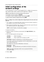
Page 32: ...y 9 Network interfaces 9 Installing and connecting user modules 10 Installing and connecting computer modules 11 Initial configuration of the network settings 12 Basic configuration of the KVM over IP...

Page 33: ...a t d branch de toutes les sources d alimentation D branchez toutes les fiches d alimentation et toutes les alimenta tions lectrique de l appareil Trennen Sie alle Spannungsversorgungen Stellen Sie vo...

Page 34: ...rce Only operate this device with an earthed voltage source Use exclusively the G D power pack Only operate this device with the power packs included in delivery or listed in this operating manual Do...

Page 35: ...o not dispose of batteries in municipal waste Check local regulations for the disposal of electronic products ATTENTION Il y a danger d explosion s il y a remplacement incorrect de la batterie Mettre...

Page 36: ...ermitted to use fibre optic modules which do not meet the requirements of laser class 1 in accordance to EN 60825 1 2014 By using such modules the compli ance with regulations and advices for the safe...

Page 37: ...Vision IP series as end devices of the IP matrix As IP user modules you can use the CON modules of the DL DVI Vision IP DP1 2 Vision IP DP Vision IP DVI Vision IP and VisionXS IP DP UHR series You ca...

Page 38: ...rk switch By listening to the IGMP conversation the switches can deter mine which of their own hosts have requested a multicast stream Only these hosts are supplied with the required multicast stream...

Page 39: ...nces when switching from one multicast group to another because for a short time both multicast streams are sent to the port Deactivation of Spanning Tree TCN Flooding When multiple network switches a...

Page 40: ...ode the target modules IP CPU send the video streams via unicast to the user modules IP CON The connection of a user to a computer to which another user is already connected is not possible in this mo...

Page 41: ...n Network interfaces Network A Plug in a category 5e or better twisted pair cable which is available as accessory Connect the other end of the cable to a network interface of the local network Network...

Page 42: ...r variants of the user modules use components with laser technology which comply with laser class 1 They meet the requirements in accordance to EN 60825 1 2014 as well as U S CFR 1040 10 and 1040 11 M...

Page 43: ...The Fiber variants of the target modules use components with laser technology which comply with laser class 1 They meet the requirements in accordance to EN 60825 1 2014 as well as U S CFR 1040 10 an...

Page 44: ...ter s web browser and enter the URL https 192 168 0 1 in the address bar 5 Enter the following data in the login mask 6 Click on Login NOTE In the defaults the following settings are pre selected IP a...

Page 45: ...itch into the local network Operational mode Use the pull down menu to select the operational mode of Interface A or Interface B Off switch network interface off Static a static IP address is being as...

Page 46: ...or operation How to add more end devices 1 Start the computer s web browser and enter the URL in the address line https IP address of the device 2 Enter the following data in the login mask 3 Click on...

Page 47: ...hich can be added to the IP matrix switch IP transmission IP address of the transmission interface IP management IP address of the management interface MAC transmission MAC address of the transmission...

Page 48: ...t possible in this mode message No multicast video You can define the type of video transmission system wide The system wide setting is applied by default by all target modules In addition you can spe...

Page 49: ...on By default the target modules IP CPU send the video stream via multicast to the user modules IP CON This option standard allows users with Target multi access right to connect to a computer to whic...

Page 50: ...he tab KVM connection system Apply system wide setting see above on This target module IP CPU sends the video stream via multi cast to other user modules IP CON This option allows users with Target mu...

Page 51: ...ocking is switched on activate the Permitted slider in the line of each device that is allowed to establish a connection to the IP matrix switch Add target module Click this button and enter the UID o...

Page 52: ...1 Turn off both power packs of the IP matrix switches 2 Press and hold the Reset button on the front panel of the device 3 Keep the button pressed and turn the device on 4 Release the button when the...

Page 53: ...the currently adjusted netfilter rules prevent access to the Config Panel web applica tion they can be can temporarily disabled in order to be edited How to disable the netfilter rules temporarily 1...

Page 54: ...age off The power pack is turned off or the connection to the mains could not be established Status Ready blinking Device is ready for operation or is being booted off Defective internal communication...

Page 55: ...ice is ready for operation or is being booted off Defective internal communication Ident on The LED to identify the device in the web application is activated Network A left flickering green Activity...

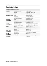
Page 56: ...power supply Type internal power pack Connector 1 IEC plug IEC 320 C14 Current consumption AC100 240V 60 50Hz Current consumption n Main power supply 400mA 240VAC 700mA 100VAC Redundant power supply...

Page 57: ...English...

Page 58: ......

Page 59: ...English...

Page 60: ...Drunck GmbH Systementwicklung Obere Leimbach 9 D 57074 Siegen Phone 49 271 23872 0 sales gdsys com www gdsys com US B ro US Office G D North America Inc 4001 W Alemada Avenue Suite 100 Burbank CA 915...

Reviews: